
Page 291 - Process Modelling and Simulation With Finite Element Methods
P. 291
278 Process Modelling and Simulation with Finite Element Methods
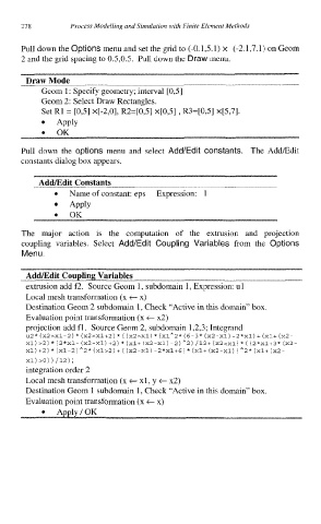
Pull down the Options menu and set the grid to (-0.1,5.1) x (-2.1,7.1) on Geom
2 and the grid spacing to 0.5,0.5. Pull down the Draw menu.
Draw Mode
Geom 1: Specify geometry; interval [0,5]
Geom 2: Select Draw Rectangles.
Set R1 = [0,51 x[-2,0], R2=[0,5] x[O,5] , R3=[0,51 X[5,71.
APPlY
OK
Pull down the options menu and select Add/Edit constants. The AddEdit
constants dialog box appears.
AddEdit Constants
Name of constant: eps Expression: 1
Apply
OK
The major action is the computation of the extrusion and projection
coupling variables. Select Add/Edit Coupling Variables from the Options
Menu.
extrusion add f2. Source Geom 1, subdomain 1, Expression: ul
Local mesh transformation (x t x)
Destination Geom 2 subdomain 1, Check “Active in this domain” box
Evaluation point transformation (x t x2)
projection add fl. Source Geom 2, subdomain 1,2,3; Integrand
*
*
*
+
(
~2* (~2>~1-2) (~2<~1+2) (x2>~1) (xlA2* (6-3* (~2-xl) -2*~1) (xl+ (~2-
*
xl) >2) * (2*x1- (x2-xl) +2) * (xl+ (X2-Xl) -2)*2) /12+ (X2<X1) ( (2*x1+3* (x2-
*
+
*
(
xl) +2) (~1-2) A2* (~1>2) (xZ-X~) -2*~1+6) (xl+ (~2-xl) *2* (xl+ (~2-
)
Xl) >O)) /12);
integration order 2
Local mesh transformation (x t xl, y t x2)
Destination Geom 1 subdomain 1, Check “Active in this domain” box.
Evaluation point transformation (x t x)
Apply/OK