
Page 127 - Rashid, Power Electronics Handbook
P. 127
114 S. Abedinpour and K. Shenai
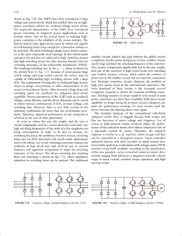
shown in Fig. 7.20. The IGBTS have been introduced at high
voltage and current levels, which has enabled their use in high-
power converters utilized for medium-voltage motor drives.
The improved characteristics of the IGBTs have introduced
power converters in megawatt power applications such as
traction drives. One of the critical issues in realizing high-
power converters is the reliability of the power switches. The
devices used in these applications must be robust and capable FIGURE 7.19 IGBT welder.
of withstanding faults long enough for a protection scheme to
be activated. The hard-switching voltage source power conver-
ter is the most commonly used topology. In this switch-mode
operation the switches are subjected to high switching stresses snubber circuits achieve this goal without the added control
and high-switching power loss that increase linearly with the complexity, but the power dissipation in these snubber circuits
switching frequency of the pulsewidth modulation (PWM). can be large and limit the switching frequency of the converter.
The resulting switching loci in the v ÿ i plane is shown by Also, passive components signi®cantly add to the size, weight,
t t
the dotted lines in Fig. 7.11. Because of simultaneous large and cost of the converter at high power levels. Soft switching
switch voltage and large switch current, the switch must be uses lossless resonant circuits, which solves the problem of
power loss in the snubber circuit, but increases the conduction
capable of withstanding high switching stresses with a large
loss. Resonant transition circuits eliminate the problem of
SOA. The requirement of being able to withstand large stresses
high peak device stress in the soft-switched converters. The
results in design compromises in other characteristics of the
main drawback of these circuits is the increased control
power semiconductor device. Often forward voltage drop and
complexity required to obtain the resonant switching transi-
switching speed are sacri®ced for enhanced short-circuit
tion. The large number of circuit variables to be sensed in such
capability. Process parameters of the IGBT such as threshold
power converters can affect their reliability. With short-circuit
voltage, carrier lifetime, and the device thickness can be varied
capability no longer being the primary concern, designers can
to obtain various combinations of SOA, on-state voltage, and
push the performance envelope for their circuits until the
switching time. However, there is very little overlap in the
device becomes the limiting factor once again.
optimum combination for more than one performance para-
The transient response of the conventional volts=hertz
meter. Therefore, improved performance in one parameter is
induction motor drive is sluggish because both torque and
achieved at the cost of other parameters.
¯ux are functions of stator voltage and frequency. Use of
In order to reduce the size, the weight, and the cost of
circuit components used in a power electronics converter very vector or ®eld-oriented control methods makes the perfor-
high switching frequencies of the order of a few megahertz are mance of the induction motor drive almost identical to that of
being contemplated. In order to be able to increase the a separately excited dc motor. Therefore, the transient
switching frequency, the problems of switch stresses, switching response is similar to a dc machine, where torque and ¯ux
losses and the EMI associated with switch-mode applications can be controlled in a decoupled manner. Vector-controlled
need to be solved. Use of soft-switching converters reduces the induction motors with shaft encoders or speed sensors have
problems of high dv=dt and high di=dt by use of external been widely applied in combination with voltage-source PWM
inductive and capacitive components to shape the switching inverters using IGBT modules. According to the speci®cation
trajectory of the device. The device-switching loci resulting of the new products, vector-controlled induction motor drive
systems ranging from kilowatts to megawatts provide a broad
from soft switching is shown in Fig. 7.11, where signi®cant
range of speed control, constant torque operation, and high
reduction in switching stress can be noticed. The traditional
starting torque.
FIGURE 7.18 Constant-voltage, constant-frequency inverter (UPS). FIGURE 7.20 Variable-voltage, variable-frequency inverter (PWM).