
Page 132 - Rashid, Power Electronics Handbook
P. 132
8 MOS Controlled Thyristors (MCTs) 119
8.2.1 Turn-on and Turn-off 1000
MCT
When the MCT is in the forward blocking state, it can be
turned on by applying a negative pulse to its gate with respect
to the anode. The negative pulse turns on the PMOSFET (On- density 100 IGBT
FET) whose drain current ¯ows through the base-emitter
junction of Q (npn) thereby turning it on. The regenerative Power BJT
1
action within Q ÿ Q turns the MCT on into full conduction Current (A/sq.cm)
1
2
within a very short time and maintains it even after the gate 10
pulse is removed. The MCT turns on without a plasma- Power MOSFET
spreading phase giving a high dI=dt capability and ease of
overcurrent protection. The on-state resistance of an MCT is
1.0
slightly higher than that of an equivalent thyristor because of
the degradation of the injection ef®ciency of the N þ 0.0 0.5 1.0 1.5 2.0 2.5
emitter=p-base junction. Also, the peak current rating of Conduction drop (volts)
an MCT is much higher than its average or rms current
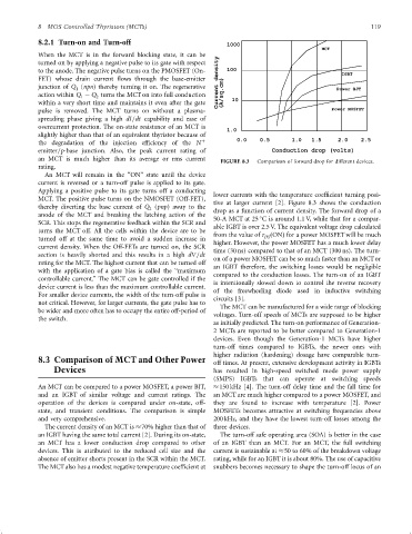
FIGURE 8.3 Comparison of forward drop for different devices.
rating.
An MCT will remain in the ‘‘ON'' state until the device
current is reversed or a turn-off pulse is applied to its gate.
Applying a positive pulse to its gate turns off a conducting
lower currents with the temperature coef®cient turning posi-
MCT. The positive pulse turns on the NMOSFET (Off-FET),
tive at larger current [2]. Figure 8.3 shows the conduction
thereby diverting the base current of Q (pnp) away to the drop as a function of current density. The forward drop of a
2
anode of the MCT and breaking the latching action of the
50-A MCT at 25 C is around 1.1 V, while that for a compar-
SCR. This stops the regenerative feedback within the SCR and
able IGBT is over 2.5 V. The equivalent voltage drop calculated
turns the MCT off. All the cells within the device are to be
from the value of r ðONÞ for a power MOSFET will be much
DS
turned off at the same time to avoid a sudden increase in
higher. However, the power MOSFET has a much lower delay
current density. When the Off-FETs are turned on, the SCR
time (30 ns) compared to that of an MCT (300 ns). The turn-
section is heavily shorted and this results in a high dV=dt
on of a power MOSFET can be so much faster than an MCTor
rating for the MCT. The highest current that can be turned off
an IGBT therefore, the switching losses would be negligible
with the application of a gate bias is called the ‘‘maximum
controllable current.'' The MCT can be gate controlled if the compared to the conduction losses. The turn-on of an IGBT
is intentionally slowed down to control the reverse recovery
device current is less than the maximum controllable current. of the freewheeling diode used in inductive switching
For smaller device currents, the width of the turn-off pulse is
circuits [3].
not critical. However, for larger currents, the gate pulse has to
The MCT can be manufactured for a wide range of blocking
be wider and more often has to occupy the entire off-period of
voltages. Turn-off speeds of MCTs are supposed to be higher
the switch.
as initially predicted. The turn-on performance of Generation-
2 MCTs are reported to be better compared to Generation-1
devices. Even though the Generation-1 MCTs have higher
turn-off times compared to IGBTs, the newer ones with
higher radiation (hardening) dosage have comparable turn-
8.3 Comparison of MCT and Other Power off times. At present, extensive development activity in IGBTs
Devices has resulted in high-speed switched mode power supply
(SMPS) IGBTs that can operate at switching speeds
An MCT can be compared to a power MOSFET, a power BJT, 150 kHz [4]. The turn-off delay time and the fall time for
and an IGBT of similar voltage and current ratings. The an MCT are much higher compared to a power MOSFET, and
operation of the devices is compared under on-state, off- they are found to increase with temperature [2]. Power
state, and transient conditions. The comparison is simple MOSFETs becomes attractive at switching frequencies above
and very comprehensive. 200 kHz, and they have the lowest turn-off losses among the
The current density of an MCT is 70% higher than that of three devices.
an IGBT having the same total current [2]. During its on-state, The turn-off safe operating area (SOA) is better in the case
an MCT has a lower conduction drop compared to other of an IGBT than an MCT. For an MCT, the full switching
devices. This is attributed to the reduced cell size and the current is sustainable at 50 to 60% of the breakdown voltage
absence of emitter shorts present in the SCR within the MCT. rating, while for an IGBT it is about 80%. The use of capacitive
The MCTalso has a modest negative temperature coef®cient at snubbers becomes necessary to shape the turn-off locus of an