
Page 134 - Rashid, Power Electronics Handbook
P. 134
8 MOS Controlled Thyristors (MCTs) 121
8.6 Simulation Model of an MCT The PMCT can only replace a P-channel IGBT and inherits all
the limitations of a P-channel IGBT. The results of a 2D
The operation of power converters can be analyzed using simulation show that the NMCT can have a higher control-
PSPICE and other simulation software. As it is a new device, lable current [13]. It is reported that NMCT versions of almost
models of MCTs are not provided as part of the simulation all Harris PMCTs have been fabricated for analyzing the
libraries. However, an appropriate model for the MCT would potential for a commercial product [3]. The NMCTs are also
be helpful in predicting the performance of novel converter being evaluated for use in zero-current soft-switching applica-
topologies and in designing the control and protection tions. However, the initial results are not quite encouraging in
circuits. Such a model must be simple enough to keep the that the peak turn-off current of an NMCT is one-half to one-
third of the value achievable in a PMCT. It is hoped that the
simulation time and effort at a minimum, and must represent
NMCTs will eventually have a lower switching loss and a larger
most of the device properties that affect the circuit operation.
SOA as compared to PMCTs and IGBTs.
The PSPICE models for Harris PMCTs are provided by the
manufacturer and can be downloaded from the internet.
However, a simple model presenting most of the character-
istics of an MCT is available [9, 10]. It is derived from the
transistor-level equivalent circuit of the MCT by expanding 8.9 Base Resistance-Controlled
the SCR model already reported the literature. The improved Thyristor [14]
model [10] is capable of simulating the breakover and break-
down characteristics of an MCT and can be used for the
The base resistance-controlled thyristor (BRT) is another gate-
simulation of high-frequency converters.
controlled device that is similar to the MCT but with a
different structure. The Off-FET is not integrated within the
p-base region but is formed within the n-base region. The
8.7 Generation-1 and Generation-2 diverter region is a shallow p-type junction formed adjacent to
MCTs the p-base region of the thyristor. The fabrication process is
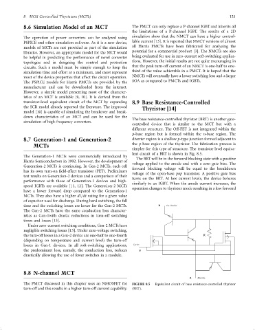
simpler for this type of structure. The transistor level equiva-
lent circuit of a BRT is shown in Fig. 8.5.
The Generation-1 MCTs were commercially introduced by
The BRTwill be in the forward blocking state with a positive
Harris Semiconductors in 1992. However, the development of
voltage applied to the anode and with a zero gate bias. The
Generation-2 MCTs is continuing. In Gen-2 MCTs, each cell
forward blocking voltage will be equal to the breakdown
has its own turn-on ®eld-effect transistor (FET). Preliminary voltage of the open-base pnp transistor. A positive gate bias
test results on Generation-2 devices and a comparison of their turns on the BRT. At low current levels, the device behaves
performance with those of Generation-1 devices and high-
similarly to an IGBT. When the anode current increases, the
speed IGBTs are available [11, 12]. The Generation-2 MCTs operation changes to thyristor mode resulting in a low forward
have a lower forward drop compared to the Generation-1
MCTs. They also have a higher dI=dt rating for a given value
of capacitor used for discharge. During hard switching, the fall
time and the switching losses are lower for the Gen-2 MCTs. K Cathode
The Gen-2 MCTs have the same conduction loss character-
istics as Gen-1with drastic reductions in turn-off switching
times and losses [13].
Under zero-current switching conditions, Gen-2 MCTs have
negligible switching losses [13]. Under zero-voltage switching,
the turn-off losses in a Gen-2 device are one-half to one-fourth R
(depending on temperature and current level) the turn-off
losses in Gen-1 devices. In all soft-switching applications, Gate
the predominant loss, namely, the conduction loss, reduces G
drastically allowing the use of fewer switches in a module.
8.8 N-channel MCT
A Anode
The PMCT discussed in this chapter uses an NMOSFET for FIGURE 8.5 Equivalent circuit of base resistance-controlled thyristor
turn-off and this results in a higher turn-off current capability. (BRT).