
Page 135 - Rashid, Power Electronics Handbook
P. 135
122 S. Yuvarajan
drop. Applying a negative voltage to its gate turns off the BRT. MCT, turns off the MTOT. The voltage pulse turns on the FET,
During the turn-off process, the anode current is diverted thereby shorting the emitter and base of the npn transistor and
þ
from the N emitter to the diverter. The BRT has a current tail breaking the regenerative action. The MTOT is a faster switch
during turn-off that is similar to an MCT or an IGBT. than a GTO in that it is turned off with a reduced storage time
compared to a GTO. The disk-type construction allows
double-side cooling.
8.10 MOS Turn-Off Thyristor [15]
The MOS turn-off (MTO) thyristor or the MTOT is a 8.11 Applications of PMCT
replacement for the GTO and it requires a much smaller
gate drive. It is more ef®cient than a GTO, it can have a
The MCTs have been used in various applications, some of
maximum blocking voltage of about 9 kV, and it will be used
which are in the area of ac-dc and ac-ac conversion where the
to build power converters in the 1- to 20-MVA range. Silicon
input is 60-Hz ac. Variable power factor operation was
Power Corporation (SPCO) manufactures the device.
achieved using the MCTs as a force-commutated power
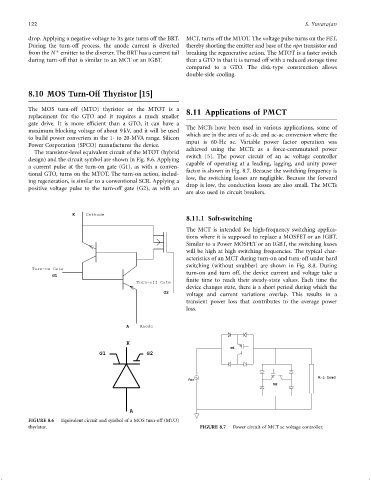
The transistor-level equivalent circuit of the MTOT (hybrid
switch [5]. The power circuit of an ac voltage controller
design) and the circuit symbol are shown in Fig. 8.6. Applying
capable of operating at a leading, lagging, and unity power
a current pulse at the turn-on gate (G1), as with a conven-
factor is shown in Fig. 8.7. Because the switching frequency is
tional GTO, turns on the MTOT. The turn-on action, includ-
low, the switching losses are negligible. Because the forward
ing regeneration, is similar to a conventional SCR. Applying a
drop is low, the conduction losses are also small. The MCTs
positive voltage pulse to the turn-off gate (G2), as with an
are also used in circuit breakers.
K Cathode
8.11.1 Soft-switching
The MCT is intended for high-frequency switching applica-
tions where it is supposed to replace a MOSFET or an IGBT.
Similar to a Power MOSFET or an IGBT, the switching losses
will be high at high switching frequencies. The typical char-
acteristics of an MCT during turn-on and turn-off under hard
switching (without snubber) are shown in Fig. 8.8. During
Turn-on Gate
turn-on and turn off, the device current and voltage take a
G1
®nite time to reach their steady-state values. Each time the
Turn-off Gate
device changes state, there is a short period during which the
G2
voltage and current variations overlap. This results in a
transient power loss that contributes to the average power
loss.
A Anode
K
M1
G1 G2
R-L load
Vac
M2
A
FIGURE 8.6 Equivalent circuit and symbol of a MOS turn-off (MTO)
thyristor. FIGURE 8.7 Power circuit of MCT ac voltage controller.