Page 131 - Rashid, Power Electronics Handbook
P. 131

118                                                                                          S. Yuvarajan

               one type, called the P-channel MCT, has been widely reported        Anode
               and is discussed here. Because the gate of the device is referred
               to with respect to the anode rather than the cathode, it is
                                                                           Metal                   Metal
               sometimes referred to as a complementary MCT (C-MCT)
               [2]. Harris Semiconductors (Intersil) originally made the  Oxide                      Oxide
               MCTs, but the MCT division was sold to Silicon Power       Gate                        Gate
               Corporation (SPCO), which has continued the development                                           Gate
               of MCTs.                                                            n+         n+
                                                                                        p+
                                                                               p                  p
               8.2 Equivalent Circuit and Switching
                    Characteristics                                           n(pnp base, Off-FET drain)

               The SCR is a 4-layer pnpn device with a control gate, and
               applying a positive gate pulse turns it on when it is forward-
               biased. The regenerative action in the device helps to speed up  p-(npn base, On-FET drain)
               the turn-on process and to keep it in the ‘‘ON'' state even after
               the gate pulse is removed. The MCT uses an auxiliary MOS
                                                                              p buffer, epitaxial layer
               device (PMOSFET) to turn on and this simpli®es the gate
               control. The turn-on has all the characteristics of a power
               MOSFET. The turn-off is accomplished using another
                                                                                   n+ substrate
                                                                                      Metal


                                                                                         Cathode
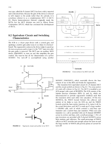
                                                                            FIGURE 8.2  Cross section of an MCT unit cell.


                                                                    MOSFET (NMOSFET), which essentially diverts the base
                                                                    current of one of the BJTs and breaks the regeneration.
                                                                      The transistor-level equivalent circuit of a P-channel MCT
                                                                    and the circuit symbol are shown in Fig. 8.1. The cross section
                                                                    of a unit cell is shown in Fig. 8.2. The MCT is modeled as an
                                                                    SCR merged with a pair of MOSFETs. The SCR consists of the
                                                                    bipolar junction transistors (BJTs) Q and Q , which are
                                                                                                    1
                                                                                                           2
                                                                    interconnected to provide regenerative feedback such that
                                                                    the transistors drive each other into saturation. Of the two
                                                                    MOSFETs, the PMOS located between the collector and
                                                                    emitter of Q helps to turn the SCR on, and the NMOS
                                                                               2
                                                                    located across the base-emitter junction of Q turns it off. In
                                                                                                         2
                                                                    the actual fabrication, each MCT is made up of a large number
                                                                    ( 100,000) cells, each of which contains a wide-base npn
                                                                    transistor and a narrow-base pnp transistor. While each pnp
                                                                    transistor in a cell is provided with an N-channel MOSFET
                                                                    across its emitter and base, only a small percentage ( 4%) of
                                                                    pnp transistors are provided with P-channel MOSFETs across
                                                                    their emitters and collectors. The small percentage of PMOS
                                                                    cells in an MCT provides just enough current for turn-on and
                                                                    the large number of NMOS cells provide plenty of current for
                    FIGURE 8.1  Equivalent circuit and symbol of an MCT.  turn-off.
   126   127   128   129   130   131   132   133   134   135   136