
Page 133 - Rashid, Power Electronics Handbook
P. 133
120 S. Yuvarajan
MCT. The addition of even a small capacitor improves the 8.5.2 Overcurrent Protection
SOA considerably.
The anode-to-cathode voltage in an MCT increases with its
anode current and this property can be used to develop a
protection scheme against overcurrent [5, 6]. The gate pulses
to the MCT are blocked when the anode current and hence the
8.4 Gate Drive for MCTs anode-to-cathode voltage exceeds a preset value. A Schmitt
trigger comparator is used to allow gate pulses to the MCT
The MCT has a MOS gate similar to a power MOSFET or an when it is in the process of turning on, during which time the
IGBT and hence it is easy to control. In a PMCT, the gate anode voltage is relatively large and decreasing.
voltage must be applied with respect to its anode. A negative
voltage below the threshold of the On-FET must be applied to
turn on the MCT. The gate voltage should fall within the
speci®ed steady-state limits in order to give a reasonably low 8.5.2.1 Snubbers
delay time and to avoid any gate damage due to overvoltage As with any other power device, the MCT is to be protected
[3]. Similar to a GTO, the gate voltage rise-time has to be against switching-induced transient voltage and current spikes
limited to avoid hot spots (current crowding) in the MCT by using suitable snubbers. The snubbers modify the voltage
cells. A gate voltage less than ÿ5 V for turn-off and greater and current transients during switching such that the switch-
than 10 V for turn-on ensures proper operation of the ing trajectory is con®ned within the safe operating area (SOA).
MCT. The latching of the MCT requires that the gate When the MCT is operated at high frequencies, the snubber
voltage be held at a positive level in order to keep the MCT increases the switching loss due to the delayed voltage and
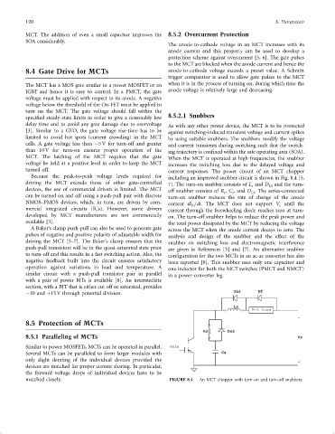
turned off. current responses. The power circuit of an MCT chopper
Because the peak-to-peak voltage levels required for including an improved snubber circuit is shown in Fig. 8.4 [5,
driving the MCT exceeds those of other gate-controlled 7]. The turn-on snubber consists of L and D LS and the turn-
s
devices, the use of commercial drivers is limited. The MCT off snubber consists of R , C , and D . The series-connected
Cs
s
s
can be turned on and off using a push-pull pair with discrete turn-on snubber reduces the rate of change of the anode
NMOS–PMOS devices, which, in turn, are driven by com- current di =dt. The MCT does not support V until the
A
s
mercial integrated circuits (ICs). However, some drivers current through the freewheeling diode reaches zero at turn-
developed by MCT manufacturers are not commercially on. The turn-off snubber helps to reduce the peak power and
available [3]. the total power dissipated by the MCT by reducing the voltage
A Baker's clamp push-pull can also be used to generate gate across the MCT when the anode current decays to zero. The
pulses of negative and positive polarity of adjustable width for analysis and design of the snubber and the effect of the
driving the MCT [5–7]. The Baker's clamp ensures that the snubber on switching loss and electromagnetic interference
push-pull transistors will be in the quasi-saturated state prior are given in References [5] and [7]. An alternative snubber
to turn-off and this results in a fast switching action. Also, the con®guration for the two MCTs in an ac-ac converter has also
negative feedback built into the circuit ensures satisfactory been reported [8]. This snubber uses only one capacitor and
operation against variations in load and temperature. A one inductor for both the MCT switches (PMCT and NMCT)
similar circuit with a push-pull transistor pair in parallel in a power-converter leg.
with a pair of power BJTs is available [8]. An intermediate
section, with a BJT that is either cut off or saturated, provides
ÿ10 and þ15 V through potential division. DLs Df
Ls
R-L Load
_
8.5 Protection of MCTs
Rs Dcs
8.5.1 Paralleling of MCTs Vs
Similar to power MOSFETs, MCTs can be operated in parallel. Gate
Several MCTs can be paralleled to form larger modules with Cs
only slight derating of the individual devices provided the +
devices are matched for proper current sharing. In particular,
the forward voltage drops of individual devices have to be
matched closely. FIGURE 8.4 An MCT chopper with turn-on and turn-off snubbers.