Page 136 - Rashid, Power Electronics Handbook
P. 136

8 MOS Controlled Thyristors (MCTs)                                                                  123

                                                                      Generation-1 MCTs did not turn on rapidly in the vicinity of
                                                                      zero anode-cathode voltage and this posed a problem in soft-
                                                                      switching applications of an MCT. However, Generation-2
                                                                      MCTs have enhanced dynamic characteristics under zero
                                                                      voltage soft switching [16]. In an MCT, the PMOS On-FET
                                                                      together with the pnp transistor constitute a p-IGBT. An
                                                                      increase in the number of turn-on cells (decrease in the on-
                                                                      resistance of the p-IGBT) and an enhancement of their
                                                                      distribution across the MCT active area enable the MCT to
                                                                      turn on at a very low transient voltage allowing zero voltage
                                                                      switching (ZVS). During zero voltage turn-on, a bipolar device
                                                                      such as the MCT takes more time to establish conductivity
                                                                      modulation. Before the device begins to conduct fully, a
                                                                      voltage spike appears, thus causing a modest switching loss
                                                                      [12]. Reducing the tail-current amplitude and duration by
                                                                      proper circuit design can minimize the turn-off losses in soft-
                                                                      switching cases.


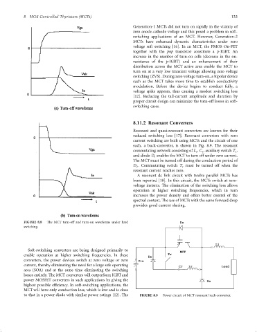
                                                                      8.11.2 Resonant Converters
                                                                      Resonant and quasi-resonant converters are known for their
                                                                      reduced switching loss [17]. Resonant converters with zero
                                                                      current switching are built using MCTs and the circuit of one
                                                                      such, a buck-converter, is shown in Fig. 8.9. The resonant
                                                                      commutating network consisting of L , C , auxiliary switch T ,
                                                                                                       r
                                                                                                                       r
                                                                                                    r
                                                                      and diode D enables the MCT to turn off under zero current.
                                                                                r
                                                                      The MCT must be turned off during the conduction period of
                                                                      D . Commutating switch T must be turned off when the
                                                                                              r
                                                                       Z
                                                                      resonant current reaches zero.
                                                                        A resonant dc link circuit with twelve parallel MCTs has
                                                                      been reported [18]. In this circuit, the MCTs switch at zero-
                                                                      voltage instants. The elimination of the switching loss allows
                                                                      operation at higher switching frequencies, which in turn
                                                                      increases the power density and offers better control of the
                                                                      spectral content. The use of MCTs with the same forward drop
                                                                      provides good current sharing.


                 FIGURE 8.8  The MCT turn-off and turn-on waveforms under hard               Dz
                 switching.


                                                                                                              L1
                   Soft-switching converters are being designed primarily to
                                                                                             MCT
                 enable operation at higher switching frequencies. In these            Tr
                                                                             Dr
                 converters, the power devices switch at zero voltage or zero  Vin
                 current, thereby eliminating the need for a large safe operating
                                                                                            Cr   Lr              Load
                 area (SOA) and at the same time eliminating the switching
                 losses entirely. The MCT converters will outperform IGBT and
                 power MOSFET converters in such applications by giving the                               Do
                 highest possible ef®ciency. In soft-switching applications, the
                 MCT will have only conduction loss, which is low and is close
                 to that in a power diode with similar power ratings [12]. The  FIGURE 8.9  Power circuit of MCT resonant buck-converter.
   131   132   133   134   135   136   137   138   139   140   141