
Page 232 - Rashid, Power Electronics Handbook
P. 232
13 DC-DC Converters 221
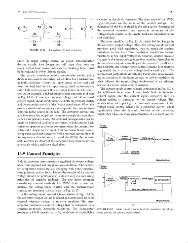
switches in the dc-dc converter. The duty ratio of the PWM
signal depends on the value of the control voltage. The
frequency of the PWM signal is the same as the frequency of
the sawtooth waveform. An important advantage of the
voltage-mode control is its simple hardware implementation
and ¯exibility.
The error ampli®er in Fig. 13.17a reacts fast to changes in
the converter output voltage. Thus, the voltage-mode control
provides good load regulation, that is, regulation against
FIGURE 13.16 Bidirectional ¯yback converter.
variations in the load. Line regulation (regulation against
variations in the input voltage) is, however, delayed because
changes in the input voltage must ®rst manifest themselves in
short the input voltage source. As power semiconductor
the converter output before they can be corrected. To alleviate
devices usually have longer turn-off times than turn-on
this problem, the voltage-mode control scheme is sometimes
times, a dead time (sometimes called a blanking time) must
augmented by a so-called voltage-feedforward path. The
be introduced in PWM driving signals.
feedforward path affects directly the PWM duty ratio accord-
The parallel combination of a controllable switch and a
ing to variations in the input voltage. As will be explained in
diode is also used in converters, which allow for a current ¯ow
what follows, the input voltage feedforward is an inherent
in both directions Ð from the input source to the load and
from the load back to the input source. Such converters are feature of current-mode control schemes.
called bidirectional power-¯ow or simply bidirectional conver- The current-mode control scheme is presented in Fig. 13.7b.
ters. As an example, a ¯yback bidirectional converter is shown An additional inner control loop feeds back an inductor
current signal, and this current signal, converted into its
in Fig. 13.16. It contains unipolar voltage and bidirectional
voltage analog, is compared to the control voltage. This
current switch-diode combinations at both the primary switch
modi®cation of replacing the sawtooth waveform of the
and the secondary switch of the ¯yback transformer. When the
voltage-mode control scheme by a converter current signal
primary switch and secondary diode operate, the current ¯ows
signi®cantly alters the dynamic behavior of the converter,
from the input source to the load. The converter current can
which then takes on some characteristics of a current source.
also ¯ow from the output to the input through the secondary
switch and primary diode. Bidirectional arrangements can be
made for both buck and boost converters. A bidirectional buck
converter operates as a boost converter when the current ¯ow
is from the output to the input. A bidirectional boost conver-
ter operates as a buck converter with a reversed current ¯ow. If
for any reason (for instance, to avoid the DCM) the control-
lable switches are driven at the same time, they must be driven
alternately with a suf®cient dead time.
13.9 Control Principles
A dc-dc converter must provide a regulated dc output voltage
under varying load and input voltage conditions. The conver-
ter component values are also changing with time, tempera-
ture, pressure, and so forth. Hence, the control of the output
voltage should be performed in a closed-loop manner using
principles of negative feedback. The two most common
closed-loop control methods for PWM dc-dc converters,
namely, the voltage-mode control and the current-mode
control, are presented schematically in Fig. 13.17.
In the voltage-mode control scheme shown in Fig. 13.17a,
the converter output voltage is sensed and subtracted from an
external reference voltage in an error ampli®er. The error
ampli®er produces a control voltage that is compared to a
constant-amplitude sawtooth waveform. The comparator FIGURE 13.17 Main control schemes for dc-dc converters: (a) voltage-
produces a PWM signal that is fed to drivers of controllable mode control; (b) current-mode control.