
Page 229 - Rashid, Power Electronics Handbook
P. 229
218 D. Czarkowski
The value of the ®lter capacitance can be calculated using To obtain the dc voltage transfer function of the converter,
Eq. (13.16). we shall use the principle that the average current through a
capacitor is zero for steady-state operation. Let us assume that
inductors L and L are large enough that their ripple current
2
1
can be neglected. Capacitor C is in steady state if
1
Á
13.6 Cuk Converter
I DT ¼ I ð1 ÿ DÞT ð13:22Þ
L1
L2
Á
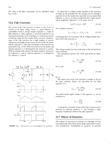
The circuit of the Cuk converter is shown in Fig. 13.12a. It
For a lossless converter
consists of dc input voltage source V , input inductor L ,
S 1
controllable switch S, energy transfer capacitor C , diode D,
1 P ¼ V I ¼ÿV I ¼ P O ð13:23Þ
O L2
S
S L1
®lter inductor L , ®lter capacitor C, and load resistance R.An
2
important advantage of this topology is a continuous current Combining these two equations, the dc voltage transfer func-
at both the input and the output of the converter. Disadvan- tion of the Cuk converter is
Á
Á
tages of the Cuk converter are a high number of reactive
components and high current stresses on the switch, the diode, V O D
and the capacitor C . The main waveforms in the converter are M V S ¼ÿ 1 ÿ D ð13:24Þ
V
1
presented in Fig. 13.12b. When the switch is on, the diode is off
and the capacitor C is discharged by the inductor L current. This voltage transfer function is the same as that for the buck-
1
2
With the switch in the off state, the diode conducts currents of boost converter.
the inductors L and L , whereas capacitor C is charged by The boundaries between the CCM and DCM are deter-
1
1
2
the inductor L current. mined by
1
ð1 ÿ DÞR
L ¼ ð13:25Þ
b1
2Df
for L and
1
ð1 ÿ DÞR
L ¼ ð13:26Þ
b2
2f
for L .
2
Á
The output part of the Cuk converter is similar to that of
the buck converter. Hence, the expression for the ®lter
capacitor C is
ð1 ÿ DÞV O
C ¼ ð13:27Þ
min 2
8V L f
r 2
The peak-to-peak ripple voltage in the capacitor C can be
1
estimated as
DV O
V ¼ ð13:28Þ
r1
C R
1 f
Á
A transformer (isolated) version of the Cuk converter can be
obtained by splitting capacitor C and inserting a high-
1
frequency transformer between the split capacitors.
13.7 Effects of Parasitics
The analysis of converters in Sections 13.2 through 13.6 has
been performed under ideal switch, diode, and passive compo-
Á
FIGURE 13.12 Cuk converter: (a) circuit diagram; (b) waveforms. nent assumptions. Nonidealities or parasitics of practical