
Page 226 - Rashid, Power Electronics Handbook
P. 226
13 DC-DC Converters 215
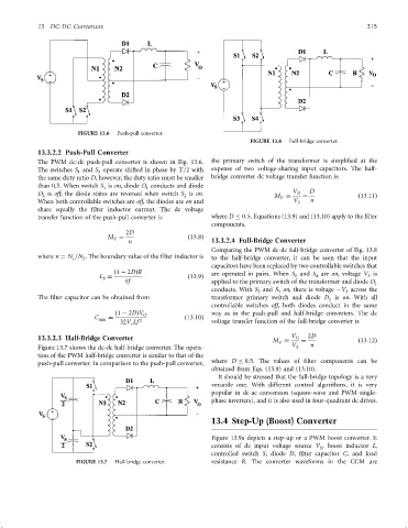
FIGURE 13.6 Push-pull converter.
FIGURE 13.8 Full-bridge converter.
13.3.2.2 Push-Pull Converter
The PWM dc-dc push-pull converter is shown in Fig. 13.6. the primary switch of the transformer is simpli®ed at the
The switches S and S operate shifted in phase by T=2 with expense of two voltage-sharing input capacitors. The half-
1
2
the same duty ratio D, however, the duty ratio must be smaller bridge converter dc voltage transfer function is
than 0.5. When switch S is on, diode D conducts and diode
1
1
D is off; the diode states are reversed when switch S is on. M V D ¼ D ð13:11Þ
2
2
V
When both controllable switches are off, the diodes are on and V S n
share equally the ®lter inductor current. The dc voltage
transfer function of the push-pull converter is where D 0:5. Equations (13.9) and (13.10) apply to the ®lter
components.
2D
M ¼ ð13:8Þ
V
n 13.3.2.4 Full-Bridge Converter
Comparing the PWM dc-dc full-bridge converter of Fig. 13.8
where n ¼ N =N . The boundary value of the ®lter inductor is
1 2 to the half-bridge converter, it can be seen that the input
capacitors have been replaced by two controllable switches that
ð1 ÿ 2DÞR are operated in pairs. When S and S are on, voltage V is
L ¼ ð13:9Þ 1 4 S
b
4f applied to the primary switch of the transformer and diode D 1
conducts. With S and S on, there is voltage ÿV across the
2 3 S
The ®lter capacitor can be obtained from transformer primary switch and diode D is on. With all
2
controllable switches off, both diodes conduct in the same
ð1 ÿ 2DÞV O way as in the push-pull and half-bridge converters. The dc
C min ¼ ð13:10Þ
32V Lf 2 voltage transfer function of the full-bridge converter is
r
13.3.2.3 Half-Bridge Converter V O 2D
M
V ¼ ð13:12Þ
Figure 13.7 shows the dc-dc half-bridge converter. The opera- V S n
tion of the PWM half-bridge converter is similar to that of the
push-pull converter. In comparison to the push-pull converter, where D 0:5. The values of ®lter components can be
obtained from Eqs. (13.9) and (13.10).
It should be stressed that the full-bridge topology is a very
versatile one. With different control algorithms, it is very
popular in dc-ac conversion (square-wave and PWM single-
phase inverters), and it is also used in four-quadrant dc drives.
13.4 Step-Up (Boost) Converter
Figure 13.9a depicts a step-up or a PWM boost converter. It
consists of dc input voltage source V , boost inductor L,
S
controlled switch S, diode D, ®lter capacitor C, and load
FIGURE 13.7 Half-bridge converter. resistance R. The converter waveforms in the CCM are