
Page 230 - Rashid, Power Electronics Handbook
P. 230
13 DC-DC Converters 219
devices and components may, however, greatly affect some
performance parameters of dc-dc converters. In this section,
the effects of parasitics on output voltage ripple, ef®ciency,
and voltage transfer function of converters will be illustrated.
A more realistic model of a capacitor than simply a
capacitance C, consists of a series connection of capacitance
C and resistance r . The resistance r is called an equivalent
C
C
series resistance (ESR) of the capacitor and is due to losses in
the dielectric and physical resistance of leads and connections.
Recall Eq. (13.6) that provided a value of the ®lter capacitance
in a buck converter that limits the peak-to-peak output voltage
ripple to V . Equation (13.6) was derived under an assumption
r
that the entire triangular ac component of the inductor
current ¯ows through a capacitance C. It is, however, closer
to reality to maintain that this triangular component ¯ows
through a series connection of capacitance C and resistance r .
C
The peak-to-peak ripple voltage is independent of the
voltage across the ®lter capacitor and is determined only by
the ripple voltage of the ESR if the following condition is
satis®ed:
1 ÿ D min D max
C C min ¼ max ; ð13:29Þ
2r f 2r f
C C
If condition Eq. (13.29) is satis®ed, the peak-to-peak ripple
voltage of the buck and forward converters is
r V ð1 ÿ D min Þ
C
O
V ¼ r Di Lmax ¼ ð13:30Þ
r
C
fL
For push-pull, half-bridge, and full-bridge converters,
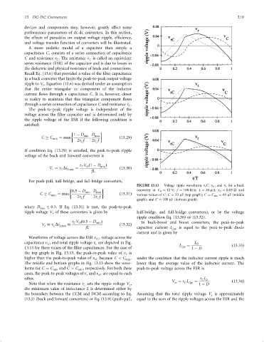
FIGURE 13.13 Voltage ripple waveforms v r C, v C , and v r for a buck
0:5 ÿ D min D max converter at V O ¼ 12 V, f ¼ 100 kHz, L ¼ 40 mH, r C ¼ 0:05 O and
C C min ¼ max ; ð13:31Þ various values of C: C ¼ 33 mF (top graph); C ¼ C min ¼ 65 mF (middle
2r f 2r f
C
C
graph); and C ¼ 100 mF (bottom graph).
where D max 0:5. If Eq. (13.31) is met, the peak-to-peak
ripple voltage V of these converters is given by half-bridge, and full-bridge converters), or by the voltage
r
ripple condition Eq. (13.30) or (13.32).
r V ð0:5 ÿ D min Þ In buck-boost and boost converters, the peak-to-peak
C
O
V ¼ r Di Lmax ¼ ð13:32Þ
C
r
fL capacitor current I Cpp is equal to the peak-to-peak diode
current and is given by
Waveforms of voltage acroos the ESR v , voltage across the
rC
capacitance v , and total ripple voltage v are depicted in Fig. I O
C
r
13.13 for three values of the ®lter capacitances. For the case of I Cpp ¼ 1 ÿ D ð13:33Þ
the top graph in Fig. 13.13, the peak-to-peak value of v is
r
higher than the peak-to-peak value of v rC because C < C min . under the condition that the inductor current ripple is much
The middle and bottom graphs in Fig. 13.13 show the wave- lower than the average value of the inductor current. The
forms for C ¼ C min and C > C min , respectively. For both these peak-to-peak voltage across the ESR is
cases, the peak-to-peak voltages of v and v rC are equal to each
r
other. r I
C O
V ¼ r I ¼ ð13:34Þ
rc
C Cpp
Note that when the resistance r sets the ripple voltage V , 1 ÿ D
r
C
the minimum value of inductance L is determined either by
the boundary between the CCM and DCM according to Eq. Assuming that the total ripple voltage V is approximately
r
(13.5) (buck and forward converters) or Eq. (13.9) (push-pull, equal to the sum of the ripple voltages across the ESR and the