
Page 282 - Rashid, Power Electronics Handbook
P. 282
272 S. Hui and H. Chung
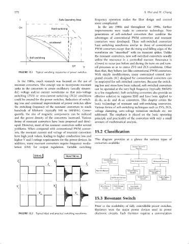
I Safe Operating Area frequency operation makes the ®lter design and control
more complicated.
On In the late 1980s and throughout the 1990s, further
Hard-switching
improvements were made in converter technology. New
generations of soft-switched converters that combine the
advantages of conventional PWM converters and resonant
converters were developed. These soft-switched converters
snubbered
have switching waveforms similar to those of conventional
PWM converters except that the rising and falling edges of the
waveforms are ‘‘smoothed'' with no transient spikes. Unlike
the resonant converters, new soft-switched converters usually
Soft-switching
utilize the resonance in a controlled manner. Resonance is
allowed to occur just before and during the turn-on and turn-
Off V off processes so as to create ZVS and ZCS conditions. Other
than that, they behave just like conventional PWM converters.
FIGURE 15.1 Typical switching trajectories of power switches.
With simple modi®cations, many customized control inte-
grated circuits (IC) designed for conventional converters can
In the 1980s, much research was focused on the use of be employed for soft-switched converters. Because the switch-
resonant converters. The concept was to incorporate resonant ing loss and stress have been reduced, soft-switched converters
tanks in the converters to create oscillatory (usually sinusoi- can be operated at the very high frequency (typically 500 kHz
dal) voltage and=or current waveforms so that zero-voltage to a few megahertz). Soft-switching converters also provide an
switching (ZVS) or zero-current switching (ZCS) conditions effective solution to suppress EMI and have been applied to
could be created for the power switches. Reduction of switch- dc-dc, ac-dc and dc-ac converters. This chapter covers the
ing loss and continual improvement of power switches allow basic technology of resonant and soft-switching converters.
the switching frequency of the resonant converters to reach Various forms of soft-switching techniques such as ZVS, ZCS,
hundreds of kilohertz (typically 100 to 500 kHz). Conse- voltage clamping, zero-voltage transition methods etc. are
quently, the size of magnetic components can be reduced addressed. The emphasis is placed on the basic operating
and the power density of the converters increased. Various principle and practicality of the converters with only a small
forms of resonant converters have been proposed and devel- amount of mathematical analysis.
oped. However, most of the resonant converters suffer several
problems. When compared with conventional PWM conver-
ters, the resonant current and voltage of resonant converters 15.2 Classification
have high peak values, leading to higher conduction loss and
higher V and I ratings requirements for the power devices. In This diagram provides at a glance the various types of
addition, many resonant converters require frequency modu- converters available:
lation (FM) for output regulation. Variable switching
15.3 Resonant Switch
Prior to the availability of fully controllable power switches,
thyristors were the major power devices used in power
FIGURE 15.2 Typical ideal and practical switching waveforms. electronic circuits. Each thyristor requires a commutation