
Page 287 - Rashid, Power Electronics Handbook
P. 287
15 Resonant and Soft-Switching Converters 277
I
Lr
Io
L L
D r f
r + +
V v D C V
i C oi f f o
r - -
+v -
c
(a)
1 cycle
I
Lr
t
I O
0 2 t
t '
t t 1 t " t t
0 1 1 t 2 ' 3 4
v c
Z I
r O
v i
0 t
t t t ' t " t t ' t t
0 1 1 1 2 2 3 4
(b)
1
0.9
0.9
0.8
0.8
0.7
0.6
0.5
M 0.5
0.4
0.3
0.2
0.2
0.1
0.1
0
0 0.1 0.2 0.3 0.4 0.5 0.6 0.7 0.8 0.9 1
g
(c)
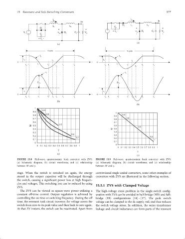
FIGURE 15.8 Half-wave, quasi-resonant buck converter with ZVS: FIGURE 15.9 Full-wave, quasi-resonant buck converter with ZVS:
(a) Schematic diagram; (b) circuit waveforms; and (c) relationship (a) Schematic diagram; (b) circuit waveforms; and (c) relationship
between M and g. between M and g.
stage. When the switch is switched on again, the energy conventional single-ended converters, some other examples of
stored in the output capacitor will be discharged through converters with ZVS are illustrated in the following section.
the switch, causing a signi®cant power loss at high frequen-
cies and voltages. This switching loss can be reduced by using 15.5.1 ZVS with Clamped Voltage
ZVS.
The ZVS can be viewed as square-wave power utilizing a The high-voltage stress problem in the single-switch con®g-
constant off-time control. Output regulation is achieved by uration with ZVS can be avoided in half-bridge (HB) and full-
controlling the on time or switching frequency. During the off bridge (FB) con®gurations [14] – [17]. The peak switch
time, the resonant tank circuit traverses the voltage across the voltage can be clamped to the dc supply rail, and thus reduces
switch from zero to its peak value and then back to zero again. the switch voltage stress. In addition, the series transformer
At that ZV instant, the switch can be reactivated. Apart from leakage and circuit inductance can form parts of the resonant