Page 291 - Rashid, Power Electronics Handbook
P. 291

15  Resonant and Soft-Switching Converters                                                          281

                     ON                                                               C
                    S                                                                  S
                     OFF                                                                    L           L
                                                                                     S                   F
                      3
                    I /I                                                             D
                    Lr  O                                                             S
                      0                                                       V i              D  C D         V o
                      -3                                                                     BUCK
                      3
                                                                                                        C
                   I /I                                                                                  D
                    S O
                                                                                     L            L
                                                                                                  F
                      0
                                                                                                        D
                                                                              V        D  S     C             V
                      -3                                                       i        S        S             o
                      5
                      4
                  V /V                                                                      BOOST
                   S  i  3
                      2                                                               C
                                                                                       S               C
                      1                                                                                 D
                      0                                                              S      L
                      3
                      2                                                              D                 D
                   I /I                                                               S
                    Df O 1                                                    V                    L          V
                      0                                                        i                    F          o
                      3
                      2
                  V /V                                                                    BUCK/BOOST
                   f  i  1
                      0
                                           t    t   t  t       t
                                           0    1   2  3       4
                                                                                   L F        L   C T    L F
                                             (a)
                      ON
                     S                                                        V i   D S  S  C S    D   C D    V o
                      OFF
                       5
                   I /I                                                                      CUK
                    Lr  O
                                                                                     C
                       0                                                              S
                                                                                           L     C       L
                                                                                    S             T       F
                       -5
                       5                                                            D
                                                                                     S
                    I /I                                                      V              L     D   C      V
                    S O                                                        i              T         D      o
                       0
                                                                                             ZETA
                       -5                                                                               C
                       5                                                                                 D
                   V /V  4                                                         L F        L   C T
                    S  i
                       3
                       2                                                                                D
                       1                                                      V     D   S   C         L       V
                       0                                                       i     S       S         T       o
                       5
                   I /I
                   Df  O
                                                                                            SEPIC
                       0
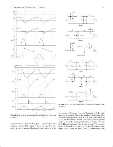
                       3                                              FIGURE 15.17  Use of the multiresonant switch in conventional PWM
                   V /V  2                                            converters.
                    f  i
                       1
                       0
                                         t      t    t  t  t
                                         0      1    2  3   4
                                             (b)                      two switches. This concept can be illustrated with the buck
                 FIGURE 15.16  Possible modes of the buck ZVS-MRC: (a) mode I; and  converter as shown in Fig. 15.19, together with the gate drive
                 (b) mode II.                                         waveforms and operating stages. Both S and S are turned on
                                                                                                      1     2
                                                                      during the time when currents ¯ow through the antiparallel
                                                                      diodes of S and S . This stage ends when S is turned off with
                                                                                     2
                                                                                                         2
                                                                               1
                 replaced with an active switch S [22]. A constant-frequency  ZVS. The ®rst resonant stage is then started. The resonant
                                            2
                 multiresonant (CF-MR) switch is shown in Fig. 15.18. The  circuit is formed by L and C . A second resonant stage
                                                                                                S2
                                                                                         r
                 output voltage is regulated by controlling the on-time of the  begins. Then L resonates with C and C . The voltage across
                                                                                  r
                                                                                                S1
                                                                                                       S2
   286   287   288   289   290   291   292   293   294   295   296