
Page 283 - Rashid, Power Electronics Handbook
P. 283
15 Resonant and Soft-Switching Converters 273
duration. The objective of this type of switch is to shape the
Lr Lr switch current waveform during conduction time in order to
create a zero-current condition for the switch to turn off [13].
Cr
S S
Cr
15.3.2 ZV Resonant Switch
(a) (b)
In a ZV resonant switch, a capacitor C is connected in parallel
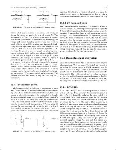
FIGURE 15.3 Two types of zero-current (ZC) resonant switch. r
with the switch S for achieving zero-voltage-switching (ZVS).
If the switch S is a unidirectional switch, the voltage across the
circuit, which usually consists of an LC resonant circuit, for capacitor C can oscillate freely in both positive and negative
r
forcing the current to zero in the turn-off process [1]. This half-cycle. Thus, the resonant switch can operate in full-wave
mechanism is in fact a type of zero-current turn-off process. mode. If a diode is connected in antiparallel with the unidir-
With recent advancements in semiconductor technology, the ectional switch, the resonant capacitor voltage is clamped by
voltage and current handling capability and the switching the diode to zero during the negative half-cycle. The resonant
speed of fully controllable switches have improved signi®- switch will then operate in half-wave mode. The objective of a
cantly. In many high-power applications, controllable switches ZV switch is to use the resonant circuit to shape the switch
such as GTOs and IGBTs have replaced thyristors [2, 3]. voltage waveform during off time in order to create a zero-
However, the use of a resonant circuit for achieving zero- voltage condition for the switch to turn on [13].
current-switching (ZCS) and=or zero-voltage-switching (ZVS)
[4 – 8] has also emerged as a new technology for power
converters. The concept of resonant switch to replace a 15.4 Quasi-Resonant Converters
conventional power switch is introduced in this section.
A resonant switch is a subcircuit composed of a semicon-
Quasi-resonant converters (QRCs) can be considered a hybrid
ductor switch S and resonant elements L and C [9 – 11].
r r of resonant and PWM converters. The underlying principle is
Switch S can be implemented by a unidirectional or bidirec-
to replace the power switch in PWM converters with the
tional switch, which determines the operation mode of the
resonant switch. A large family of conventional converter
resonant switch. Two types of resonant switches [12], includ- circuits can be transformed into their resonant converter
ing zero-current (ZC) resonant switch and zero-voltage (ZV) counterparts. The switch current and=or voltage waveforms
resonant switches, are shown in Fig. 15.3 and Fig. 15.4, are forced to oscillate in a quasi-sinusoidal manner, so that ZCS
respectively. and=or ZVS can be achieved. Both ZCS-QRCs and ZVS-QRCs
have half-wave and full-wave modes of operation [8 – 10, 12].
15.3.1 ZC Resonant Switch
15.4.1 ZCS-QRCs
In a ZC resonant switch, an inductor L is connected in series
r
with a power switch S in order to achieve zero-current-switch- A ZCS-QRC designed for half-wave operation is illustrated
ing (ZCS). If the switch S is a unidirectional switch, the switch with a buck-type dc-dc converter. The schematic is shown in
current is allowed to resonate in the positive half-cycle only. Fig. 15.5a. It is formed by replacing the power switch in a
The resonant switch is said to operate in half-wave mode. If a conventional PWM buck converter with the ZC resonant
diode is connected in antiparallel with the unidirectional switch in Fig. 15.3a. The circuit waveforms in steady state
switch, the switch current can ¯ow in both directions. In this are shown in Fig. 15.5b. The output ®lter inductor L is
f
case, the resonant switch can operate in full-wave mode. At suf®ciently large so that its current is approximately constant.
turn-on, the switch current will rise slowly from zero. It will Prior to turning the switch on, the output current I free-
o
then oscillate because of the resonance between L and C . wheels through the output diode D . The resonant capacitor
r
r
f
Finally, the switch can be commutated at the next zero current voltage V Cr equals zero. At t , the switch is turned on with
0
ZCS. A quasi-sinusoidal current I ¯ows through L and C ,
r
S
r
the output ®lter, and the load. Then S is softly commutated at
Lr Lr t with ZCS again. During and after the gate pulse, the
1
resonant capacitor voltage V Cr rises and then decays at a
Cr rate depending on the output current. Output voltage regula-
S S tion is achieved by controlling the switching frequency. Opera-
Cr
tion and characteristics of the converter depend mainly on the
(a) (b)
design of the resonant circuit L ÿ C . The following para-
r
r
FIGURE 15.4 Two types of zero-voltage (ZV) resonant switch. meters are de®ned: voltage conversion ratio M, characteristic