
Page 149 - Renewable Energy Devices and System with Simulations in MATLAB and ANSYS
P. 149
136 Renewable Energy Devices and Systems with Simulations in MATLAB and ANSYS ®
®
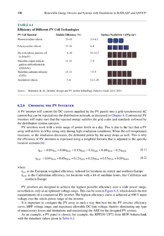
TABLE 6.1
Efficiency of Different PV Cell Technologies
PV Cell Material Module Efficiency (%) Surface Needed for 1 kWp (m )
2
Monocrystalline silicon 15–18 5.5–6.5
Polycrystalline silicon 13–16 6–8
Micromorphous tandem cell 8–10 10–12.5
(a-Si/ucSi)
Thin-film copper indium/ 11–15 7–9
gallium sulfur/diselenide
(CI/GS/Se)
Thin-film cadmium telluride 11–13 7.5–9
(CdTe)
Amorphous silicon 5–8 12.5–20
Source: Remmers, K.-H., Inverter, storage and PV system technology, Industry Guide 2014, 2014.
6.2.6 Choosing the PV Inverter
A PV inverter will convert the DC current supplied by the PV panels into a grid-synchronized AC
current that can be injected into the distribution network, as discussed in Chapter 4. Commercial PV
inverters will make sure that the injected energy satisfies the grid codes and standards enforced by
the distribution system operator.
PV inverters work with a wide range of power levels in a day. This is due to the fact that a PV
array will deliver its kWp rating only during high irradiation conditions. When the cell temperature
increases, or the irradiation decreases, the delivered power by the array drops as well. This is why
the efficiency of PV inverters is expressed using a weighted formula that is adjusted to the specific
location scenario [6]:
η
.
.
.
.
.
.
η EU = 003 5% + 0 06 η 10% + 013 η 20% + 0 1 η 30% + 0 48 η 50% + 02 η 100% (6.1)
η
.
.
.
.
.
.
η CEC = 004 10% + 0 05 η 20% + 012 η 30% + 0 21 η 50% + 053 η 75% + 0 05 η 100% (6.2)
%
where
η EU is the European weighted efficiency, tailored for locations in central and northern Europe
η CEC is the Californian efficiency, for locations with a lot of sunshine hours, like California and
southern Europe
PV inverters are designed to achieve the highest possible efficiency over a wide power range,
nevertheless, only at an optimum voltage range. This can be seen in Figure 6.5, which details the test
measurements of a commercial PV inverter. The highest efficiency curve is achieved at 600 V input
voltage over the whole power range of the inverter.
It is important to configure the PV array in such a way that best fits the PV inverter efficiency
curve, MPP voltage range, and maximum allowable DC-link voltage, thereby eliminating any type
of unnecessary losses and limitations and maximizing the AEP for the designed PV system.
As an example, a PV panel is chosen, for example, the RPP250 UP72 from REW Solartechnik
with the datasheet values given in Table 6.2.