
Page 153 - Renewable Energy Devices and System with Simulations in MATLAB and ANSYS
P. 153
140 Renewable Energy Devices and Systems with Simulations in MATLAB and ANSYS ®
®
Array yield:
Y A = E A (6.4)
P G0
where
E A is the DC energy of the PV system
P G0 is the nominal power of the PV system at STC
The array yield only takes into account the losses up to the DC side of the PV inverter.
Reference yield:
Y R = H G = H G (6.5)
G 0 G STC
where
H G is the total insolation over the predefined period
2
G STC is the insolation at STC: 1000 W/m ; 25 C; AM 15
.
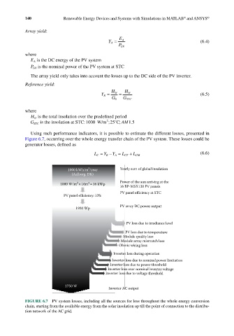
Using such performance indicators, it is possible to estimate the different losses, presented in
Figure 6.7, occurring over the whole energy transfer chain of the PV system. These losses could be
generator losses, defined as
L C = Y R − Y A = L CT + L CM (6.6)
2
1000 kWh/m /year Yearly sum of global insolation
(Aalborg, DK)
2
2
1000 W/m ×16m =16 kWp Power of the sun arriving at the
16 BP-MSX120 PV panels
PV panel efficiency at STC
PV panel efficiency: 12%
PV array DC power output
1920 Wp
PV loss due to irradiance level
PV loss due to temperature
Module quality loss
Module array mismatch loss
Ohmic wiring loss
Inverter loss during operation
Inverter loss due to nominal power limitation
Inverter loss due to power threshold
Inverter loss over nominal inverter voltage
Inverter loss due to voltage threshold
1750 W
Inverter AC output
FIGURE 6.7 PV system losses, including all the sources for loss throughout the whole energy conversion
chain, starting from the available energy from the solar insolation up till the point of connection to the distribu-
tion network of the AC grid.