
Page 146 - Semiconductor Manufacturing Handbook
P. 146
Geng(SMH)_CH11.qxd 04/04/2005 19:48 Page 11.3
WET ETCHING
WET ETCHING 11.3
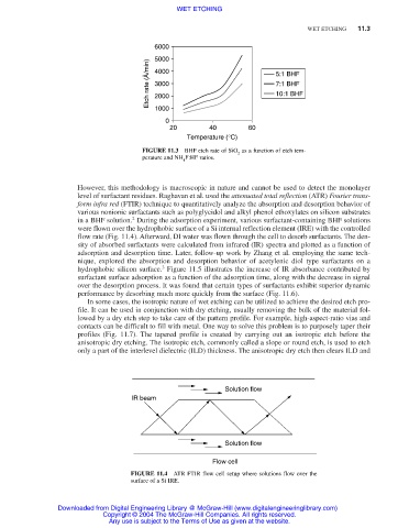
6000
5000
Etch rate (Å/min) 4000 5:1 BHF
7:1 BHF
3000
10:1 BHF
2000
1000
0
20 40 60
Temperature (°C)
FIGURE 11.3 BHF etch rate of SiO as a function of etch tem-
2
perature and NH F:HF ratios.
4
However, this methodology is macroscopic in nature and cannot be used to detect the monolayer
level of surfactant residues. Raghavan et al. used the attenuated total reflection (ATR) Fourier trans-
form infra red (FTIR) technique to quantitatively analyze the absorption and desorption behavior of
various nonionic surfactants such as polyglycidol and alkyl phenol ethoxylates on silicon substrates
2
in a BHF solution. During the adsorption experiment, various surfactant-containing BHF solutions
were flown over the hydrophobic surface of a Si internal reflection element (IRE) with the controlled
flow rate (Fig. 11.4). Afterward, DI water was flown through the cell to desorb surfactants. The den-
sity of absorbed surfactants were calculated from infrared (IR) spectra and plotted as a function of
adsorption and desorption time. Later, follow-up work by Zhang et al. employing the same tech-
nique, explored the absorption and desorption behavior of acetylenic diol type surfactants on a
3
hydrophobic silicon surface. Figure 11.5 illustrates the increase of IR absorbance contributed by
surfactant surface adsorption as a function of the adsorption time, along with the decrease in signal
over the desorption process. It was found that certain types of surfactants exhibit superior dynamic
performance by desorbing much more quickly from the surface (Fig. 11.6).
In some cases, the isotropic nature of wet etching can be utilized to achieve the desired etch pro-
file. It can be used in conjunction with dry etching, usually removing the bulk of the material fol-
lowed by a dry etch step to take care of the pattern profile. For example, high-aspect-ratio vias and
contacts can be difficult to fill with metal. One way to solve this problem is to purposely taper their
profiles (Fig. 11.7). The tapered profile is created by carrying out an isotropic etch before the
anisotropic dry etching. The isotropic etch, commonly called a slope or round etch, is used to etch
only a part of the interlevel dielectric (ILD) thickness. The anisotropic dry etch then clears ILD and
Solution flow
IR beam
Solution flow
Flow cell
FIGURE 11.4 ATR FTIR flow cell setup where solutions flow over the
surface of a Si IRE.
Downloaded from Digital Engineering Library @ McGraw-Hill (www.digitalengineeringlibrary.com)
Copyright © 2004 The McGraw-Hill Companies. All rights reserved.
Any use is subject to the Terms of Use as given at the website.