
Page 179 - Semiconductor Manufacturing Handbook
P. 179
Geng(SMH)_CH13.qxd 04/04/2005 19:50 Page 13.2
PHYSICAL VAPOR DEPOSITION
13.2 WAFER PROCESSING
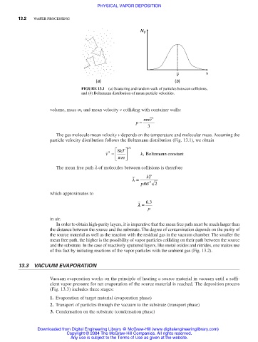
N V
– v
v
(a) (b)
FIGURE 13.1 (a) Scattering and random walk of particles between collisions,
and (b) Boltzmann distribution of mean particle velocities.
volume, mass m, and mean velocity v colliding with container walls:
p = nmv 2
3
The gas molecule mean velocity v depends on the temperature and molecular mass. Assuming the
particle velocity distribution follows the Boltzmann distribution (Fig. 13.1), we obtain
8 kT 12 /
v = k, Boltzmann constant
2
p m
The mean free path λ of molecules between collisions is therefore
l = kT
p ps 2 2
which approximates to
.
l = 63
p
in air.
In order to obtain high-purity layers, it is imperative that the mean free path must be much larger than
the distance between the source and the substrate. The degree of contamination depends on the purity of
the source material as well as the reaction with the residual gas in the vacuum chamber. The smaller the
mean free path, the higher is the possibility of vapor particles colliding on their path between the source
and the substrate. In the case of reactively sputtered layers, like metal oxides and nitrides, one makes use
of this fact by initiating reactions of the vapor particles with the ambient gas (Fig. 13.2).
13.3 VACUUM EVAPORATION
Vacuum evaporation works on the principle of heating a source material in vacuum until a suffi-
cient vapor pressure for net evaporation of the source material is reached. The deposition process
(Fig. 13.3) includes three stages:
1. Evaporation of target material (evaporation phase)
2. Transport of particles through the vacuum to the substrate (transport phase)
3. Condensation on the substrate (condensation phase)
Downloaded from Digital Engineering Library @ McGraw-Hill (www.digitalengineeringlibrary.com)
Copyright © 2004 The McGraw-Hill Companies. All rights reserved.
Any use is subject to the Terms of Use as given at the website.