
Page 180 - Semiconductor Manufacturing Handbook
P. 180
Geng(SMH)_CH13.qxd 04/04/2005 19:50 Page 13.3
PHYSICAL VAPOR DEPOSITION
PHYSICAL VAPOR DEPOSITION 13.3
100 0 20
Percentage of vapor particles passing the distance r without collision % 60 r 40 % collisions while passing the distance r Percentage of vapor particles experiencing
80
60
40
20
100
0 80
100 50 10 5 1 0.5 0.1
−
l
r
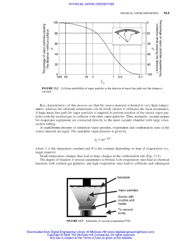
FIGURE 13.2 Collision probability of vapor particles as the function of mean free path over the distance r
traveled. 1
Key characteristics of this process are that the source material is heated to very high temper-
atures, whereas the substrate temperature can be freely chosen to influence the layer parameters.
A large mean free path for vapor particles is required to prevent reaction of the source vapor par-
ticles with the residual gas or collision with other vapor particles. Thus, normally, vacuum pumps
for evaporator equipment are connected directly to the main vacuum chamber with large cross-
section tubing.
At equilibrium pressure or saturation vapor pressure, evaporation and condensation rates of the
source material are equal. The saturation vapor pressure is given by
p = Ae − ( BT / )
s
where A is the integration constant and B is the constant depending on heat of evaporation, i.e.,
target material.
Small temperature changes thus lead to large changes in the condensation rate (Fig. 13.4).
The degree of freedom in process parameters is limited. Low evaporation rates lead to chemical
reactions with residual gas particles, and high evaporation rates lead to collisions and subsequent
Substrate
Vapor particles
Source with
crucible and
heater
To vacuum
pump
FIGURE 13.3 Schematic of vacuum evaporation PVD.
Downloaded from Digital Engineering Library @ McGraw-Hill (www.digitalengineeringlibrary.com)
Copyright © 2004 The McGraw-Hill Companies. All rights reserved.
Any use is subject to the Terms of Use as given at the website.