
Page 63 - Semiconductor Manufacturing Handbook
P. 63
Geng(SMH)_CH06.qxd 04/04/2005 19:37 Page 6.2
PLASMA PROCESS CONTROL
6.2 SEMICONDUCTOR FUNDAMENTALS AND BASIC MATERIALS
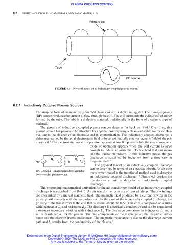
Primary coil
Tube
RF source
FIGURE 6.1 Physical model of an inductively coupled plasma source.
6.2.1 Inductively Coupled Plasma Sources
The simplest form of an inductively coupled plasma source is shown in Fig. 6.1. The radio frequency
(RF) source produces the current to flow through the coil. The coil surrounds the cylindrical chamber
formed by the tube. The tube is a dielectric material, traditionally in the form of a ceramic type of
material.
1
The genesis of inductively coupled plasma sources dates as far back as 1884. Over time, this
plasma source has proven to be attractive for applications requiring a clean and stable source of plas-
ma, due to the absence of an electrode and its contamination. The inductively coupled discharge is
either maintained by the axial electrostatic field or by an azimuthally electromagnetic field of the pri-
2
mary coil. The electrostatic mode of operation appears at low RF power while the electromagnetic
mode of operation appears when the coil current is large
enough to induce an azimuthal electric field that can main-
tain the ionization process. In this inductive mode, the gas
discharge is sustained by induction from a time-varying
R R
V RF o L o L 2 2 L e magnetic field. 3
The physical model of an inductively coupled discharge
can be described in terms of an electrical circuit. An air core
FIGURE 6.2 Electrical model of an induc- transformer model is the traditional method used to describe
tively coupled plasma source.
an inductively coupled discharge. 4–6 Figure 6.2 depicts the
transformer circuit to describe an inductively coupled
discharge.
The proceeding mathematical derivation for the air transformer model of an inductively coupled
discharge is transcribed from Ref. 3. An air transformer consists of two windings. These windings
are interlinked by a mutual magnetic field. The magnetic field produced by a current flowing in the
primary coil interacts with the secondary coil. In the case of the inductively coupled discharge, the
primary of the transformer is the coil that is wound about the tube. This coil is composed of N turns
with inductance L and resistance R . The discharge is electrically conductive and can be considered
o o
a one-turn secondary winding with inductance L . The discharge comprises an inductance L and a
2 e
series resistance R for the plasma. The two components of the discharge are the magnetic induc-
2
tance and the electron inertia inductance. The magnetic inductance is due to the discharge current
path and L results from the conductivity of the plasma. 7
e
Downloaded from Digital Engineering Library @ McGraw-Hill (www.digitalengineeringlibrary.com)
Copyright © 2004 The McGraw-Hill Companies. All rights reserved.
Any use is subject to the Terms of Use as given at the website.