
Page 130 - Separation process principles 2
P. 130
3.4 Molecular Diffusion in Laminar Flow 95
Assume the following values for physical properties: build up as shown at planes b, c, and d. In this region, the
central core outside the boundary layer has a flat velocity
Vapor pressure of napthalene = 10 torr
Viscosity of air = 0.0215 cP profile where the flow is accelerated over the entrance ve-
Molar density of air = 0.0327 kmol/m3 locity. Finally, at plane e, the boundary layer fills the tube.
Diffusivity of napthalene in air = 0.94 x m2/s From here the velocity profile is fixed and the flow is said to
be fully developed. The distance from the plane a to plane e
SOLUTION is the entry region.
For fully developed laminar flow in a straight, circular
(a) NRe, = 5 x lo5 for transition. From (3-127), tube, by experiment, the Reynolds number, NRe = Dii, p /p,
where ii, is the flow-average velocity in the axial direction,
x, and D is the inside diameter of the tube, must be less than
2,100. For this condition, the equation of motion in the axial
at which transition to turbulent flow begins.
direction for horizontal flow and constant properties is
10(0'0327) = 4.3 10-4 hoyrn3
(b) CA~ = 0 CA, =
760
From (3-lol),
where the boundary conditions are
P [(0.0215)(0.001)]
-
-
Nsc = - = 2.41 r = 0 (axis of the tube), au,/ar = 0
pDAB [(0.0327)(29)](0.94 x
and r = r,(tube wall), u, = 0
From (3- 137),
Equation (3-139) was integrated by Hagen in 1839 and
Nshavg = 0.664(5 x 10~)~/~(2.41)~/~ = 630
Poiseuille in 1841. The resulting equation for the velocity
From (3-138), profile, expressed in terms of the flow-average velocity, is
For a width of 1 m,
or, in terms of the maximum velocity at the tube axis,
A = 2.27 m2
(c) From (3-129), at x = L = 2.27 m, From the form of (3-141), the velocity profile is parabolic in
nature.
The shear stress, pressure drop, and Fanning friction fac-
tor are obtained from solutions to (3-139):
From (3-135),
dP 32pii, 2 fpii:
Fully Developed Flow in a Straight, Circular Tube - - (3-143)
dx D2 D
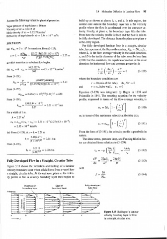
Figure 3.15 shows the formation and buildup of a laminar
with
velocity boundary layer when a fluid flows from a vessel into
a straight, circular tube. At the entrance, plane a, the veloc- f=- 16
ity profile is flat. A velocity boundary layer then begins to NR~
Thickness of Edge of Fully developed
boundary layer boundary layer tube flow
Entr
Figure 3.15 Buildup of a laminar
u b c d e velocity boundary layer for flow
-X in a straight, circular tube.