
Page 205 - Separation process principles 2
P. 205
170 Chapter 5 Cascades and Hybrid Systems
Makeup
absorbent Makeup
1 I I absorbent
+-
Absorber
-III-I Stripper Absorber
Entering
Entering
vapor (e.g., steam or
other inert gas) vapor
,
Recycle absorbent
Recycle absorbent
Makeup
q
absorbent
-
Absorber
Entering
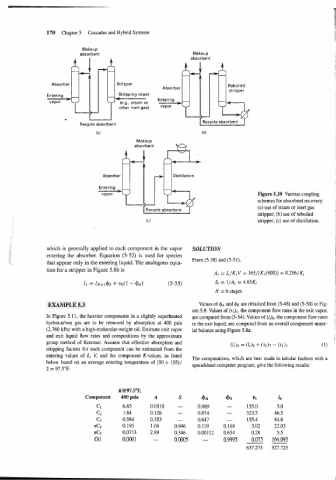
vapor Figure 5.10 Various coupling
. schemes for absorbent recovery:
f
Recycle absorbent (a) use of steam or inert gas
stripper; (b) use of reboiled
stripper; (c) use of distillation.
which is generally applied to each component in the vapor SOLUTION
entering the absorber. Equation (5-52) is used for species
From (5-38) and (5-51),
that appear only in the entering liquid. The analogous equa-
tion for a stripper in Figure 5.8b is
Ai = L/Ki V = 165/[Ki(800)] = 0.206/K1
11 = ~N+I$S + vo(1 - $A) (5-55) Si = 1/A; = 4.85Ki
N = 6 stages
Values of $A and are obtained from (5-48) and (5-50) or Fig-
ure 5.9. Values of (v,),, the component flow rates in the exit vapor,
In Figure 5.11, the heavier components in a slightly superheated are computed from (5-54). Values of the component flow rates 1
hydrocarbon gas are to be removed by absorption at 400 psia in the exit liquid, are computed from an overall component mater- !
(2,760 kPa) with a high-molecular-weight oil. Estimate exit vapor ial balance using Figure 5.8a:
and exit liquid flow rates and compositions by the approximate
i
group method of Kremser. Assume that effective absorption and
(1116 = (&)o + (21117 - (vi)1 (1)
stripping factors for each component can be estimated from the
entering values of L, V, and the component K-values, as listed
The computations, which are best made in tabular fashion with a
below based on an average entering temperature of (90 + 105)/
spreadsheet computer program, give the following results:
2 = 97.5"F.
K@97.S°F,
Component 400 psia
c 1 6.65
c2 1.64
c3 0.584
nC4 0.195
nCs 0.0713
Oil 0.0001