
Page 207 - Separation process principles 2
P. 207
172 Chapter 5 Cascades and Hybrid Systems
mole fraction is reduced from 0.866 to 0.815, but hexane Total
Total condenser
recovery is increased to 36.1(0.815)/50 or 58.8%. condenser 163.5"~. D = 36.1 Distillate
=
Q = 874 MBH XH~ 0.872
Both of the successive flash arrangements in Figure 5.12 Reflux, L,
involve a considerable number of heat exchangers and
pumps. Except for stage 1, the heaters in Figure 5.12a
can be eliminated if the two intermediate total con-
densers are converted to partial condensers with duties
Stage 2
of 734 - 487 = 247 MBH (MBH = 1,000 Btulh) and section
483 - 376 = 107 MBH. Total heating duty is now oilly
751,000 Btuk, and total cooling duty is 731,000 Btulh.
Stage 1 Stage
Similarly, if heaters for stages 2 and 3 in Figure 5.12b are 215OF Feed ;a
removed by converting the two total condensers to partial F= 100 Q = 904 MBH -
Feed AT\ 63.9
T, = 192.3'F xH: i0.290
condensers, total heating duty is 904,000 Btuk (20% greater XHZ = 0.50
than the no-recycle case), and cooling duty is 864,000 Btuk Boiler (a)
(18% greater than the no-recycle case).
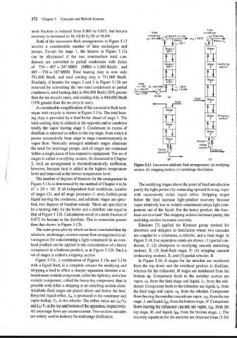
A considerable simplification of the successive flash tech-
Stage
nique with recycle is shown in Figure 5.13a. The total heat-
ing duty is provided by a feed boiler ahead of stage 1. The section
total cooling duty is utilized at the opposite end to condense
Stage
totally the vapor leaving stage 3. Condensate in excess of H
distillate is returned as reflux to the top stage, from which it Stage
passes successively from stage to stage countercurrently to Stage
Boilup V,
vapor flow. Vertically arranged adiabatic stages eliminate
the need for interstage pumps, and all stages are contained Partial rebo~ler Bottoms
within a single piece of less expensive equipment. The set of reboiler
parti7 +
stages is called a rectifiing section. As discussed in Chapter
2, such an arrangement is thermodynanlically inefficient, Figure 5.13 Successive adiabatic flash arrangements: (a) rectifying
however, because heat is added at the highest temperature section; (b) stripping section; (c) multistage distillation.
level and removed at the lowest temperature level.
The number of degrees of freedom for the arrangement in
Figure 5.13a is determined by the method of Chapter 4 to be The rectifying stages above the point of feed introduction
(C + 2N + 10). If all independent feed conditions, number purify the light product by contacting upward flowing vapor
of stages (3), and all stage pressures (1 atm), bubble-point with successively richer liquid reflux. Stripping stages
liquid leaving the condenser, and adiabatic stages are speci- below the feed increase light-product recovery because
fied, two degrees of freedom remain. These are specified to vapor relatively low in volatile constituents strips light com-
be a heating duty for the boiler and a distillate rate equal to ponents out of the liquid. For the heavy product, the func-
that of Figure 5.12b. Calculations result in a mole fraction of tions are reversed: The stripping section increases purity; the
0.872 for hexane in the distillate. This is somewhat greater enriching section increases recovery.
than that shown in Figure 5.12b. Edmister [3] applied the Kremser group method for
The same principles by which we have concluded that the absorbers and strippers to distillation where two cascades
adiabatic, multistage, countercurrent-flow arrangement is ad- are coupled to a condenser, a reboiler, and a feed stage. In
vantageous for concentrating a light component in an over- Figure 5.14, five separation zones are shown: (1) partial con-
head product can be applied to the concentration of a heavy denser, C; (2) absorption or rectifying cascade (enriching
component in a bottoms product, as in Figure 5.13b. Such a section), E; (3) feed-flash stage, F; (4) stripping cascade
set of stages is called a stripping section. (exhausting section), X; and (5) partial reboiler, B.
Figure 5.13c, a combination of Figures 5.13a and 5.13b In Figure 5.14, N stages for the enricher are numbered
with a liquid feed, is a complete column for rectifying and from the top down and the overhead product is distillate;
stripping a feed to effect a sharper separation between a se- whereas for the exhauster, M stages are numbered from the
lected more volatile component, called the light key, and a less bottom up. Component feeds to the enricher section are
volatile component, called the heavy key component, than is vapor, vfi from the feed stage and liquid, lc, from the con-
possible with either a stripping or an enriching section alone. denser. Component feeds to the exhauster are liquid, LA from
Adiabatic flash stages are placed above and below the feed. the feed stage and vapor, v~, from the reboiler. Component
Recycled liquid reflux, LR, is produced in the condenser and flows leaving the enricher cascade are vapor, UTE, from the top
vapor boilup, V1, in the reboiler. The reflux ratios are LR/VN stage, 1, and liquid, lBE, from the bottom stage, N. Component
and L2/V1 at the top and bottom of the apparatus, respectively. flows leaving the exhauster cascade are vapor, vm, from the
All interstage flows are countercurrent. Two-section cascades top stage, M, and liquid, lBx, from the bottom stage, 1. The
are widely used in industry for multistage distillation. recovery equations for the enricher are obtained from (5-54)