
Page 210 - Separation process principles 2
P. 210
5.5 Membrane Cascades 175
-
Feed +I-%-- Retentate - Retentate
-
Feed
7
Stage 4
I Stage 3
t
Stage 2
Stage 1 T T t
Stage 1 Permeate
(a) One stage (b) Multiple stage
Figure 5.16 Parallel units of membrane separators.
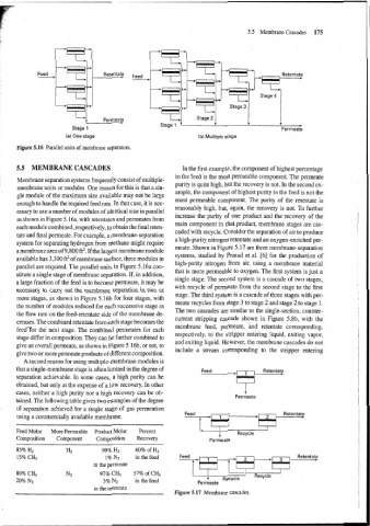
5.5 MEMBRANE CASCADES In the first example, the component of highest percentage
in the feed is the most permeable component. The permeate
Membrane separation systems frequently consist of multiple-
membrane units or modules. One reason for this is that a sin- purity is quite high, but the recovery is not. In the second ex-
ample, the component of highest purity in the feed is not the
gle module of the maximum size available may not be large
most permeable component. The purity of the retentate is
enough to handle the required feed rate. In that case, it is nec-
reasonably high, but, again, the recovery is not. To further
essary to use a number of modules of identical size in parallel
increase the purity of one product and the recovery of the
as shown in Figure 5.16a, with retentates and permeates from
main component in that product, membrane stages are cas-
each module combined, respectively, to obtain the final reten-
caded with recycle. Consider the separation of air to produce
tate and final permeate. For example, a membrane-separation
a high-purity nitrogen retentate and an oxygen-enriched per-
system for separating hydrogen from methane might require
meate. Shown in Figure 5.17 are three membrane-separation
amembrane area of 9,800 ft2. If the largest membrane module
available has 3,300 ft2 of membrane surface, three modules in systems, studied by Prasad et al. [6] for the production of
high-purity nitrogen from air, using a membrane material
parallel are required. The parallel units in Figure 5.16a con-
that is more permeable to oxygen. The first system is just a
stitute a single stage of membrane separation. If, in addition,
single stage. The second system is a cascade of two stages,
a large fraction of the feed is to become permeate, it may be
with recycle of permeate from the second stage to the first
necessary to carry out the membrane separation in two or
stage. The third system is a cascade of three stages with per-
more stages, as shown in Figure 5.16b for four stages, with
meate recycles from stage 3 to stage 2 and stage 2 to stage 1.
the number of modules reduced for each successive stage as
The two cascades are similar to the single-section, counter-
the flow rate on the feed-retentate side of the membrane de-
current stripping cascade shown in Figure 5.8b, with the
creases. The combined retentate from each stage becomes the
feedl'ror the next stage. The combined permeates for each membrane feed, permeate, and retentate corresponding,
respectively, to the stripper entering liquid, exiting vapor,
stage differ in composition. They can be further combined to
and exiting liquid. However, the membrane cascades do not
give an overall permeate, as shown in Figure 5.16b, or not, to
include a stream corresponding to the stripper entering
give two or more permeate products of different composition.
A second reason for using multiple-membrane modules is
that a single-membrane stage is often limited in the degree of Retentate
separation achievable. In some cases, a high purity can be
obtained, but only at the expense of a low recovery. In other
cases, neither a high purity nor a high recovery can be ob- P- Permeate
tained. The following table gives two examples of the degree
of separation achieved for a single stage of gas permeation
using a commercially available membrane.
Feed Molar More Permeable Pro'duct Molar Percent + Recycle
Composition Component Composition Recovery Permeate
85% H2 H2 99% H2 60% of H2
15% CH4 1% N2 in the feed
in the permeate
1
80% CH4 N2 97% C& 57% of C& - Recycle Recycle '
20% N2 3% N2 in the feed Permeate
in the retentate
Figure 5.17 Membrane cascades.