
Page 324 - Shigley's Mechanical Engineering Design
P. 324
bud29281_ch06_265-357.qxd 11/30/2009 4:23 pm Page 299 pinnacle s-171:Desktop Folder:Temp Work:Don't Delete (Jobs):MHDQ196/Budynas:
Fatigue Failure Resulting from Variable Loading 299
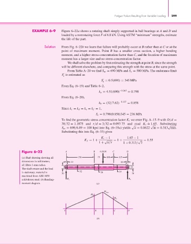
EXAMPLE 6–9 Figure 6–22a shows a rotating shaft simply supported in ball bearings at A and D and
loaded by a nonrotating force F of 6.8 kN. Using ASTM “minimum” strengths, estimate
the life of the part.
Solution From Fig. 6–22b we learn that failure will probably occur at B rather than at C or at the
point of maximum moment. Point B has a smaller cross section, a higher bending
moment, and a higher stress-concentration factor than C, and the location of maximum
moment has a larger size and no stress-concentration factor.
We shall solve the problem by first estimating the strength at point B, since the strength
will be different elsewhere, and comparing this strength with the stress at the same point.
From Table A–20 we find S ut = 690 MPa and S y = 580 MPa. The endurance limit
S is estimated as
e
S = 0.5(690) = 345 MPa
e
From Eq. (6–19) and Table 6–2,
k a = 4.51(690) −0.265 = 0.798
From Eq. (6–20),
k b = (32/7.62) −0.107 = 0.858
Since k c = k d = k e = k f = 1,
S e = 0.798(0.858)345 = 236 MPa
To find the geometric stress-concentration factor K t we enter Fig. A–15–9 with D/d =
.
38/32 = 1.1875 and r/d = 3/32 = 0.093 75 and read K t = 1.65. Substituting
√ √ √
S ut = 690/6.89 = 100 kpsi into Eq. (6–35a) yields a = 0.0622 in = 0.313 mm.
Substituting this into Eq. (6–33) gives
K t − 1 1.65 − 1
K f = 1 + √ = 1 + √ = 1.55
1 + a/r 1 + 0.313/ 3
Figure 6–22 A B 6.8 kN C D
(a) Shaft drawing showing all 250 75 100 125
dimensions in millimeters; 10 10
all fillets 3-mm radius.
The shaft rotates and the load
32 35
is stationary; material is 38
30 30
machined from AISI 1050
R R
cold-drawn steel. (b) Bending- 1 2
moment diagram. (a)
M max
M B
M
C
A B C D
(b)