
Page 326 - Shigley's Mechanical Engineering Design
P. 326
bud29281_ch06_265-357.qxd 11/30/2009 4:23 pm Page 301 pinnacle s-171:Desktop Folder:Temp Work:Don't Delete (Jobs):MHDQ196/Budynas:
Fatigue Failure Resulting from Variable Loading 301
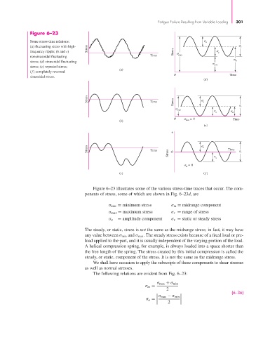
Figure 6–23
Some stress-time relations: a
(a) fluctuating stress with high- Stress r
frequency ripple; (b and c) Stress a
nonsinusoidal fluctuating Time max
stress; (d) sinusoidal fluctuating m
min
stress; (e) repeated stress;
(a)
(f) completely reversed
O Time
sinusoidal stress.
(d)
Stress Time Stress a
r
max
a m
O = 0 Time
(b) min
(e)
+
Stress Time a Time
Stress O a r
= 0
m
(c) ( f )
Figure 6–23 illustrates some of the various stress-time traces that occur. The com-
ponents of stress, some of which are shown in Fig. 6–23d, are
σ min = minimum stress σ m = midrange component
σ max = maximum stress σ r = range of stress
σ a = amplitude component σ s = static or steady stress
The steady, or static, stress is not the same as the midrange stress; in fact, it may have
any value between σ min and σ max . The steady stress exists because of a fixed load or pre-
load applied to the part, and it is usually independent of the varying portion of the load.
A helical compression spring, for example, is always loaded into a space shorter than
the free length of the spring. The stress created by this initial compression is called the
steady, or static, component of the stress. It is not the same as the midrange stress.
We shall have occasion to apply the subscripts of these components to shear stresses
as well as normal stresses.
The following relations are evident from Fig. 6–23:
σ max + σ min
σ m =
2
(6–36)
σ max − σ min
σ a =
2