
Page 125 - Six Sigma for electronics design and manufacturing
P. 125
Six Sigma for Electronics Design and Manufacturing
94
To construct a cause and effect diagram:
Use brainstorming to identify all possible causes for the effect. Ask
outside experts to add to the list produced by brainstorming.
Review the list and look for any interrelationships between the pos-
sible causes. Define three to six major categories that can be
grouped together and categorize them. Common categories are
sometimes referred to as the four M’s: Materials, Machines, Meth-
ods and Manpower.
Within each category, further subdivision might be required based
on relationship or cause. They can ultimately be divided into sub-
groups.
Draw the diagram, using arrows and names of each group, sub-
group, and individual cause.
Evaluate and select the most probable cause(s), based on the prob-
lem solving group decision tools.
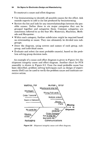
An example of a cause and effect diagram is given in Figure 3.6, the
shipment integrity cause and effect diagram. Another chart for PCB
assembly is shown in Figure 8.2. Once the most probable cause has
been identified, problem solving techniques such as design of experi-
ments (DoE) can be used to verify the problem cause and institute cor-
rective action.
Figure 3.6 Shipment integrity cause and effect diagram.