
Page 129 - Six Sigma for electronics design and manufacturing
P. 129
Six Sigma for Electronics Design and Manufacturing
98
Use regression analysis to accurately determine degree of correlation
and the “best fit line.” Significance can be determined using tech-
niques similar to those shown on the next chapter.
3.4.1.7 Histograms. Histograms are pictures of the frequency distri-
bution of a process. They are bar graphs with the height of each col-
umn representing the number of occurrences in each step for the
process or measurement.
3.4.1.7.1 Information from histograms. By drawing the process specifica-
tion on the axes, histograms clearly show the position of the process
relative to desired performance. It becomes clear whether the process
is performing as desired, or that the process average needs to be shift-
ed, or the distribution needs to be narrowed.
One of the problems in plotting histograms is determining the best
2
fit for a probability distribution. The Goodness of fit test, discussed
in Chapter 2, is a good method to test the histogram to a specific dis-
tribution.
Figure 8.4 is an example of a histogram presentation of data for the
improvement of a PCB soldering process, before and after a DoE was
performed to improve the process.
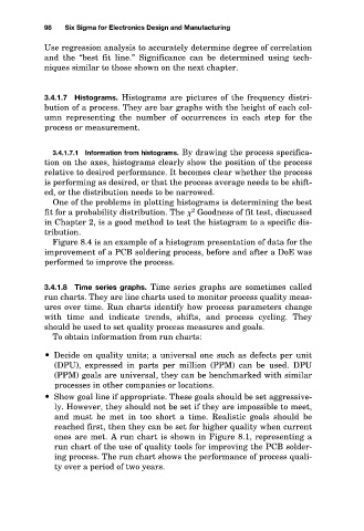
3.4.1.8 Time series graphs. Time series graphs are sometimes called
run charts. They are line charts used to monitor process quality meas-
ures over time. Run charts identify how process parameters change
with time and indicate trends, shifts, and process cycling. They
should be used to set quality process measures and goals.
To obtain information from run charts:
Decide on quality units; a universal one such as defects per unit
(DPU), expressed in parts per million (PPM) can be used. DPU
(PPM) goals are universal, they can be benchmarked with similar
processes in other companies or locations.
Show goal line if appropriate. These goals should be set aggressive-
ly. However, they should not be set if they are impossible to meet,
and must be met in too short a time. Realistic goals should be
reached first, then they can be set for higher quality when current
ones are met. A run chart is shown in Figure 8.1, representing a
run chart of the use of quality tools for improving the PCB solder-
ing process. The run chart shows the performance of process quali-
ty over a period of two years.