Page 120 - The Geological Interpretation of Well Logs
P. 120

-  THE  GEOLOGICAL  INTERPRETATION  OF  WELL  LOGS  ~

                                                          for  8,  or  two  for  32  waveforms  and  using  one  monopole
                                                          transmitter  for  8  waveforms  using  either  ‘a  high  frequen-
                                                          cy  signal  for  P  and  $  waves  or  a  low  frequency  signal  for
                                                          Stoneley  wave  detection.  The  tool  acquires  digital  wave-
                                                          form  data  with  5]2  samples  per  waveform.  Logging
                                                          speed  varies  but  can  be  at  a  maximum  of  1100m/hr  (3600
                                                          fv/hr)  which  is  similar  to  the  standard  nuclear  tools.
                                                            All  tools  using  an  array  of  receivers  acquire  a  number
                                                          of  receiver  (or  transmitter)  common  measurements  at
                                                          each  depth  station  (Figure  8.31),  the  number  of  common
                                                          datapoints  depending  on  the  number  of  receivers  and/or
                                                          transmitters  used.  Receiver  threshold  detection,  as  used  in
                                                          the  standard  tools,  is  inadequate  and  inappropriate  for  the
             b)
                                                          full  waveform  tool.  Instead,  a  full,  digital  waveform  is
                                                          recorded  and  gathering  techniques  are  used  to  collect
                                                          the  common  datapoints  from  a  single  depth  {or  selected
                                                          interval).  The  gathering  may  be  made  using  one  transmit-
              Ss  WA             :S WAVE                  ter  position  and  a  full  receiver  array  (Smith  er  ai.,  1991)
                                        DIPOLE
                                                          (Figure  8.31),  or  a  sub-array  as  used  by  Schlumberger,
                                                          when  several  consecutive  transmitter  and  receiver  points
                                                          are  used  (Hsu  &  Chang,  1987)  (Figure  8.32).  Sampling
                                                          depths  are  normally  the  same  as  the  separation  between
                                                          the  receivers  of  the  array,  typically  15.24cm  (6").
                                                          However,  since,  gathering  may  be  over  an  interva]  cover-
                                                          ing  several  receivers  as  described,  the  effective  interval
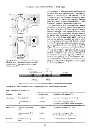
        Figure  8.29  Array  sonic  transmitter  types.  a}  monopole   being  measured  depends  on  the  gathering  process  (Figure
        transmitter  giving  a  multi-directional  pulse;  b)  dipole   8.32),  as  discussed  below.
        transmitter  giving  a  directed  pulse  {modified  from
        Zemanek  ef  ai.,  1991).
                                   dipole               receiver
                                 transmitters            array
                                                         13.6%   1

                                           (41'}
                                     2                         |              cartridge
                                               ———_+

                        |         id > i]           ve  ws  2  2           jinn
                                             ix)  ——+|    ~—
                                                           (671
                                       monopole          recelvar
                                       transmitter       spacing
                        ati.
                        <<
                           tool  length  15.6m  (54°)  —————
        Figure  8.30  The  Dipole  Shear  Imager  Tool  of  Schlumberger  (re-drawn  from  Schlumberger  document).
        Table  8.7  Full  waveform  acoustic  tools.

        Company       Tool                      Receiver  Array   Transmitters  &  Frequency  (Fq)

        Schlumberger   Array  Sonic  ASL        8  receivers     2  wansmitters,  monopole,  Fq  =  10-15  kHz

                       Dipole  Shear  Imager    8  receivers     3  iransmitiers,  |  monopole,  2  dipole
                       DSI                                       Fg  =  |  kHz  (diopole),  Fq  =  variable  (mononpole)

        Atlas  Wireline   Digital  Array  Acoustilog   2  receivers   2  wansmitters,  monopole,  Fq  =  9  kHz
                       DAC

                       Multipole  Acoustic  Tool   8  receivers   4  transmitters,  2  monopole,  2  dipole
                       MAC                                       Fq  =  1-3  Hz  (dip),  Fq  =  8  kHz  (mono)

        Halliburton    Full  Wave  Sonic  Log   4  receivers     1  wansmitter,  monopole,  Fq  =  13  kHz
                        FWS

                                                       110
   115   116   117   118   119   120   121   122   123   124   125