
Page 119 - The Geological Interpretation of Well Logs
P. 119
- SONIC OR ACOUSTIC LOGS -
SONIC VELOCITY SONIC REFLECTION REFLECTION SYNTHETIC waveform tool exist, those with standard monopole or
VELOCITY COEFFICIENT COEFFICIENT SeISMOGRAM
OR WITH multi-directional transmitters and those with dipole
ACOUSTIC TRANSMISSION
= IMPEDANCE LOSSES (polarised) transmitters which are better adapted to shear
)
e/aT———~
+
=
—-
-
+
wave detection.
The desired output from the full waveform sonic is
either some form of waveform plot against depth or a
continuous log of discrete values of the slowness of the
—
compressional (P), shear (S} and Stoneley (St) waves.
Slowness {the reciprocal of velocity) is the average wave
lag between two consecutive receivers (or transmitters)
corresponding to the difference in wave arrival times at
each of the receivers and given in j/ft or p/m. From these
and their inter-relationships such as Poisson’s ratio,
information can be extracted on fractures, permeability,
¥ '
lithology, porosity and fluid content.
_—— Full waveform toats
One of the difficulties in full waveform sonic logging
is the identification of the shear wave arrival. Typical
time
transmitters and receivers in the standard sonic are multi-
sepin aime
directional (monopole), emitting sound waves equally in
lime all directions around the too] (Figure 8.292). With this
transmission mode, in certain so called ‘slaw’ formations
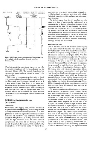
Figure 8.28 Diagrammatic representation of the constuction
of a synthetic seismic trace from the sonic log. (From (that is when the shear wave velocity, refracted from the
Thomas, 1977). formation, is the same or less than the borehole fluid
velocity), the shear and fluid arrivals cannot be separated.
Using monopole or multi-directional transmitters, there-
When both a sonic log and a density Jog are run in a well, fore, may not allow a direct detection of shear waves. For
the acoustic impedances of the layers logged can be this reason, tools exist with dipole transmitters able to
calculated (Figure 8.28). The acoustic impedance log provide a direct shear wave detection in both ‘slow’ and
represents the logged section as it would be sensed by the ‘fast’ formations. Dipole transmitters are non-axisymmet-
seismic pulse, ric and produce sound waves which are directed, the
With the aid of a computer, a synthetic seismic signal transmitted pulse giving a positive displacement to the
is formulated and passed through the acoustic impedance borehole fluid (push) in one direction and an equal, neg-
log. The seismic signal is distorted just as it would be if ative displacement (pull) in the opposite direction (Figure
it were going through these layers in the subsurface. 8.29b). Monopole and dipole transmitters are used in
Recording the signal distortions, the computer constructs different tools (Table 8.7} although they may also be
a synthetic seismic response (Figure 8.28). The original combined in one tool.
sonic data have been converted into a seismic trace. The Full waveform tool design differs between companies
synthetic seismic log ts invaluable for ‘tying’ wells to and is evolving. A common feature, however, is the
the seismic, and demonstrating the effective resolution on need for an array of receivers, 12 in the Atlas tool, 8 in
the section. the Schlumberger tool (Figure 8.30} and four in the
Haliburton tool (Table 8.7). At least 8 receivers seem to
8.8 Full waveform acoustic logs be preferable (Smith et af.,)991). The Schlumberger
Dipole Shear Sonic Imager (DSI) can be used as an
(array sonic)
example. This too] has an array of eight receivers. Jt has
Generalities two dipole transmitters at right angles to each other,
The standard sonic logging tools, available for the last 3.35m and 3.5m (lft and 11.5ft) from the nearest
40 years and described previously, measure only the first receiver and one monopole transmitter 2.7m (9ft) from
or compressional (P) wave arrival (Section 8.2). A new the receivers (Figure 8.30). The monopole transmitter is
generation of tools with a great deal more sophistication used with a low frequency pulse for Stoneley wave
measure a full waveform. They tend to be called array detection and a high frequency pulse for P and S wave
sonic tools through the use of an array of receivers which detection. The dipole wansmitters use a low frequency
under the right conditions, allow the identification of pulse (Table 8.7). The array of 8 receivers spans 1.07m
compressional (P), shear (S) and Stoneley (St) wave (3.5ft), with a 15.24cem (6") spacing between each one.
arrivals (Figure 8.2). For reasons, which will be briefly For full waveform acquisition, the too] may operate in a
explained (see Full waveform tools), two types of full number of different modes: using one dipole transmitter
109