
Page 118 - The Geological Interpretation of Well Logs
P. 118
- THE GEOLOGICAL INTERPRETATION OF WELL LOGS -
Velocity kftisec
5 19 7a
a sco psoetit gg] 50 100 150 350 400 S$ Ps,
|
tyra
tig
a
pliriirtipryr
Zo oO
pot
|
1
l
|
tt
Joi}
l
ot
Jet
debe!
a
1
|
Jot
= re
= me
2 ks
o
g | J
1900 | —]
Ta
—“ ¢
o
“oa
a
— a
42
2000 | —|
(seconds}
3000]
time
4S @
+c
{io
=~ oOo
¢
ao00|—] iwo-way
48
je
jo
s0oe —}
|
6000
|
do]
7000 | =
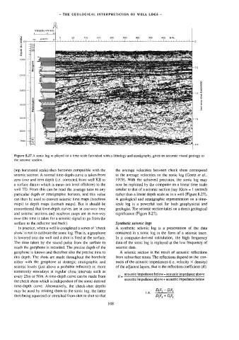
Figure 8.27 A sonic log re-played on a lime scale furnished with a lithology and stratigraphy, gives an accurate visual geology to
the seismic section.
(top horizontal scale) then becomes compatible with the the average velocities between check shots correspond
seismic section. A normal time-depth curve is taken from to the average velocities on the sonic log (Goetz ef ai.,
zero time and zero depth (i.e. corrected from well KB to 1979), With the achieved precision, the sonic log may
a surface datum which is mean sea level offshore) to the now be replotied by the computer on a linear time scale
weil TD. From this can be read the average time to any similar to that of a seismic section (say 1Ocm = | second)
particular depth or stratigraphic horizon, and this value rather than a linear depth scale as in a well (Figure 8.27).
can then be used to convert seismic time maps (isochron A geological and stratigraphic representation on a time-
maps) to depth maps (isobath maps). But it should be scale log is a powerful tool for both geophysicist and
remembered that time-depth curves are in one-way time geologist. The seismic section takes on a direct geological
and seismic sections and isochron maps are in fvo-way significance (Figure 8.27).
time (the time it takes for a seismic signal to go from the
surface to the reflector and back). Synthetic seismic logs
In practice, when a well is completed a series of ‘check A synthetic seismic log is a presentation of the data
shots’ is run to calibrate the sonic log. That is, a geophone contained in a sonic log in the form of a seismic trace.
is lowered into the well and a shot is fired at the surface. In a computer-derived calculation, the high frequency
The time taken by the sound pulse from the surface to data of the sonic log is replayed at the low frequency of
reach the geophone is recorded. The precise depth of the seismic data.
geophone is known and therefore also the precise time to A seismic section is the result of acoustic reflections
this depth. The shots are made throughout the boretiole from subsurface strata. The reflections depend on the con-
either with the geophone at strategic stratigraphic and trasts of the acoustic impedances (i.e. velocity X density)
seismic levels (just above a probable reflector) or, more of the adjacent layers, that is the reflection coefficient (R):
commonly nowadays at regular close intervals such as
Re acoustic impedance below acoustic impedance above
every 25m or 50m. A time-depth curve can be made from
acoustic impedance above+ acoustic impedance below
the check shots which is independent of the sonic-derived
time-depth curve. Alternatively, the check-shot depths
~
DV,
may be used by relating them to the sonic log, the latter DV,
1.€.
then being squeezed or stretched from shot to shot so that DY, + DY,
108