
Page 82 - The Geological Interpretation of Well Logs
P. 82
- THE GEOLOGICAL INTERPRETATION OF WELL LOGS ~
a mix contributes 24.27 API units, and so on. The SGR is
GAMMA RAY -
therefore the sum of these API contributions {and can be
API _
remembered as the Sum Gamma Rays). The CGR, or o 50 100
oO { L 1 1 1 } I 1
computed gamma ray curve, represents the contributions
tool
of only the thorium and potassium in API units. Hence, centred
the difference between the SGR and the CGR is the con-
@-
tribution, in API units, of uranium. For reasons explained
below (Section 7.10), the CGR is considered to be an
improved clay volume indicator to the total (SGR) API
count (and can be remembered as the Clay Gamma Ray).
In formats not described here, curves of the different
elemental ratios can be displayed. 25 4
Depth of investigation
The depth from which radiations can be detected by the
E
simple gamma ray tool is generally small but difficult
s
to be precise about. One experiment found that 75% of
o ™
radiations detected came from a 14 cm radius and 25 cm 8 e)
vertically above and below the detector. This was for eaccentred
gamma rays with a single energy of 1.76 MeV and the tool
50
detector centralised in a 15 cm diameter hole filled with
hole size 12%”
1.2 cn density mud (Rhodes and Mott, 1966). Clearly,
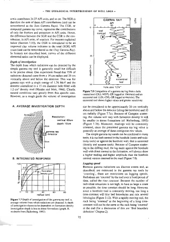
Figure 7.8 Comparison of a gamma ray log from a hole
natural conditions vary greatly from this specific case.
centred tool (DLL-MSFL-GR logged at 106m/min) and an
However, as a rough guide the volume of investigation
eccentred tool (LDL-CNL-GR logged at 4m/min). The
eccentred too] shows higher values and greater sensitivity.
A. AVERAGE INVESTIGATION DEPTH can be considered to be approximately 20 cm vertically
above and below the detector (along the borehole) and 10
cm radially (Figure 7.7a). Because of Compton scatter-
Resolution: ing, this volume will vary with formation density: it will
vertical 40cm be smaller in dense formations (cf. Hallenburg, 1992}
depth 10cm (Figure 7.75). Moreover, readings will be commonly
smeared, since the presented gamma ray ‘og value is
generally an average of three contiguous raw values.
The simple gamma ray sonde can be combined in many
tools; it is run both centred in the borehole (sonic and resis-
tivity tools) or against the borehole wall, that is eccentred
(density and neutron tools). Because of Compton scatter-
ing in the drilling mud, the log made against the borehole
wall with direct contact to the formation, will always show
a higher reading and higher amplitude than the borehole
B. INTEGRATED RESPONSE centred version emersed in the mud (Figure 7.8).
100 Logging speed
I
ee
pan)
3.0 YH 20) Because gamma radiations are discrete events and, as
\
described, are measured in the gamma ray tools by
LY x
response Tt density gem? Radiations are ‘counted’ by the tool over a fixed period of
Formatlan
‘counting’, there are restrictions on logging speeds.
TV
time, called the time constant. Because the number of
% i individual emissions is not high, to have as large a count
as possible, the time constant should be long. However,
since a borehole tool is constantly moving, too long a
0 10 20 40 60 80
radius (cm) time-constant wil] blur bed boundaries and mix several
lithologies (Figure 2.12). With a rapidly moving tool, the
Figure 7.7 Depth of investigation of the gamma ray tool. a.
rock being ‘counted’ at the beginning of a long time-
average volume from which radiations are detected. b. depth
constant will not be the same as the rock being ‘counted’
of investigation shown to be dependent on formation density.
Investigation depth is less in dense formations (graph. B, at the end (for a discussion of this see ‘Bed boundary
re-drawn from Hajlenberg, 1992). definition’ Chapter 2).
72