
Page 1138 - The Mechatronics Handbook
P. 1138
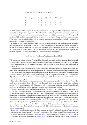
TABLE 42.1  Predicate Definition Truth Table
                                                                               P out
                                                       Comparison  U  U   OR    OR   AND   AND
                                                   P in
                                                    0      0      0   0   —     —     —     —
                                                    0      1      0   0   —     —     —     —
                                                    1      0      0   1   —     1      0    —
                                                    1      1      1   0    1    —     —      0


                                 an instruction should modify the state, is stored in a set of 1-bit registers. These registers are collectively
                                 referred to as the predicate register file. The values in the predicate register file are associated with each
                                 instruction in the extended instruction set through the use of an additional source operand. This operand
                                 specifies which predicate register will determine whether the operation should modify the processor state.
                                 If the value in the specified register is 1, or true, the instruction is executed normally; if the value is 0,
                                 or false, the instruction is suppressed.
                                   Predicate register values may be set using predicate define instructions. The predicate define semantics
                                                                    8
                                 used are those of the HPL Playdoh architecture.  There is a predicate define instruction for each comparison
                                 opcode in the original instruction set. The major difference with conventional comparison instructions is
                                 that these predicate defines have up to two destination registers and that their destination registers are
                                 predicate registers. The instruction format of a predicate define is shown below.

                                                                                          (
                                                    pred_ <cmp> Pout1 <type> ,Pout2 <type> ,scr1,scr2 P in )
                                 This instruction assigns values to Pout1 and Pout2 according to a comparison of src1 and src2 specified
                                 by <cmp>. The comparison <cmp> can be: equal (eq), not equal (ne), greater than (gt), etc. A predicate
                                 <type> is specified for each destination predicate. Predicate defining instructions are also predicated, as
                                 specified by P in .
                                   The predicate <type> determines the value written to the destination predicate register based upon the
                                 result of the comparison and of the input predicate, P in . For each combination of comparison result and
                                 P in , one of the three following actions may be performed on the destination predicate: it can write 1, write
                                 0, or leave it unchanged. There are six predicate types which are particularly useful, the unconditional
                                 (U), OR, and AND type predicates and their complements. Table 42.1 contains the truth table for these
                                 predicate definition types.
                                   Unconditional destination predicate registers are always defined, regardless of the value of P in  and the
                                 result of the comparison. If the value of P in  is 1, the result of the comparison is placed in the predicate
                                 register (or its compliment for  ). Otherwise, a 0 is written to the predicate register. Unconditional
                                                          U
                                 predicates are utilized for blocks, which are executed based on a single condition.
                                   The OR-type predicates are useful when execution of a block can be enabled by multiple conditions,
                                 such as logical AND (&&) and OR (||) constructs in C. OR-type destination predicate registers are set if
                                 P in  is 1 and the result of the comparison is 1 (0 for OR ); otherwise, the destination predicate register is
                                 unchanged. Note that OR-type predicates must be explicitly initialized to 0 before they are defined and
                                 used. However, after they are initialized, multiple OR-type predicate defines may be issued simultaneously
                                 and in any order on the same predicate register. This is true since the OR-type predicate either writes a
                                 “1” or leaves the register unchanged, which allows implementation as a wired logical OR condition. AND-
                                 type predicates are analogous to the OR type predicate. AND-type destination predicate registers are
                                 cleared if P in  is 1 and the result of the comparison is 0 (1 for AND); otherwise, the destination predicate
                                 register is unchanged.
                                   Figure 42.11 contains a simple example illustrating the concept of predicated execution. Figure 42.11(a)
                                 shows a common programming “if-then-else” construction. The related control flow representation of
                                 that programming code is illustrated in Fig. 42.11(b). Using if-conversion, the code in Fig. 42.11(b) is
                                 then transformed into the code shown in Fig. 42.11(c). The original conditional branch is translated into


                                 ©2002 CRC Press LLC