
Page 881 - The Mechatronics Handbook
P. 881
0066-frame-C29 Page 11 Wednesday, January 9, 2002 7:23 PM
1.5
2 pole
5 pole
Magnitude 0.5 10 pole
1
0
0 0.2 0.4 0.6 0.8 1 1.2 1.4 1.6 1.8 2
w
0
-200
Angle (degrees) -400
-600
-800
-1000
0 0.2 0.4 0.6 0.8 1 1.2 1.4 1.6 1.8 2
w
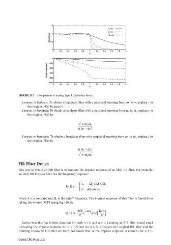
FIGURE 29.7 Comparison of analog Type I Chebyshev filters.
Lowpass to highpass: To obtain a highpass filter with a passband running from ω 1 to ∞, replace s in
the original H(s) by ω 1 ω c /s.
Lowpass to bandpass: To obtain a bandpass filter with a passband running from ω 1 to ω 2 , replace s in
the original H(s) by
s + w 2 w 1
2
-------------------------.
s w 2 –( w 1 )
Lowpass to bandstop: To obtain a bandstop filter with stopband running from ω 1 to ω 2 , replace s in
the original H(s) by
(
s w 2 – w 1 )
-------------------------.
s + w 2 w 1
2
FIR Filter Design
One way to obtain an FIR filter is to truncate the impulse response of an ideal IIR filter. For example,
an ideal IIR lowpass filter has the frequency response:
A, −Ω c ≤ Ω ≤ Ω c
H Ω() =
0, otherwise
where A is a constant and Ω c is the cutoff frequency. The impulse response of this filter is found from
taking the inverse DTFT using Eq. (29.3):
Ω c n
hn[] = AΩ c jnΩ /2 sinc ---------
c
----------e
p p
Notice that this has infinite duration for both n < 0 and n > 0. Creating an FIR filter would entail
truncating the impulse response for n < −N and for n > N. However, the original IIR filter and the
resulting truncated FIR filter are both noncausal; that is, the impulse response is nonzero for n < 0.
©2002 CRC Press LLC