Page 882 - The Mechatronics Handbook
P. 882
0066-frame-C29 Page 12 Wednesday, January 9, 2002 7:23 PM
Noncausal filters need future values of the input in order to calculate the present value of the output;
hence, they cannot be implemented in real-time. For this reason, typical IIR design uses nonideal filters
(often based on analog prototypes) that approximate the ideal frequency response. When filtering a signal
off-line that has been stored, causality is no longer required since all of the values of the signal are available
(including “future” values).
In order to perform real-time implementation of an FIR filter that was generated by truncating an
ideal IIR filter, the filter must be delayed so that all of the significant information of the impulse response
occurs for n ≥ 0. This delay in the time domain is equivalent to a linear phase lag in the frequency domain.
Thus, an FIR filter can be designed by first selecting an ideal IIR filter (lowpass, highpass, etc.), then
taking the inverse DTFT to find the impulse response, and then truncating the impulse response, and finally,
delaying it in time. An equivalent and more preferred method is to rearrange the steps described above.
First, add a phase lag in the frequency response of the ideal IIR filter. This is done by multiplying the
frequency response by e j(N − 1)/2 . Then, take the inverse DTFT and truncate it for n < 0 and n > N − 1. The
result is a causal FIR filter with order N.
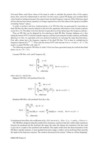
The following are generic FIR filters of order N that have been generated using the method described
above. Let m = (N − 1)/2.
Lowpass FIR filter with cutoff frequency Ω c :
Ω c n = 0
------,
p
hn[] = Ω c Ω c nm)
(
–
------sinc ------------------------- , for 0 < n ≤ N 1
–
p p
0, otherwise
where sinc(x) = sin(πx)/πx.
Highpass FIR filter with passband from Ω 1 :
1 – Ω 1 0
------, for n =
p
h n[] = Ω 1 Ω 1 nm–( )
–
−------sinc ------------------------- 0, for 0 < n ≤ N 1
p p
0, otherwise
Bandpass FIR filter with passband from Ω 1 to Ω 2 :
Ω 2 – Ω 1
-------------------, for N = 0
p
hn[] = Ω 2 Ω 1
(
–
–
------ sinc Ω 2 nm–([ )/p ] – ------sin [ Ω 1 nm)/p ], for 0 < n ≤ N 1
p p
0, otherwise
To implement these filters, the coefficients in Eq. (29.5) are set to b m = h[m − 1], a 1 = 1, and a m = 0 for m > 1.
The FIR filters designed using this method have frequency responses that have rather sharp transitions
between the passband and the stopband (the larger the order, the sharper the transition), but they tend
to give rise to a ripple in the passband and stopband. This ripple results from the sharp truncation of the
IIR filter’s impulse response. A more gradual truncation using a window can be performed that smooths
the ripple in the frequency response. The windows discussed in the section “s-Plane to z-Plane Mappings”
©2002 CRC Press LLC

