Page 928 - The Mechatronics Handbook
P. 928
0066_Frame_C30  Page 39  Thursday, January 10, 2002  4:44 PM


                       sensitivity and complementary sensitivity singular values are desirable in that they suggest that the target
                       loop will possess:
                          • good low frequency command following properties,
                          • good low frequency disturbance attenuation properties,
                          • good high frequency sensor noise attenuation properties, and
                          • good MIMO stability margins (nearly infinite upward gain margin, at least 6 dB downward gain
                            margin, and at least ±60° phase margin) at the output.
                       The complementary sensitivity singular values suggest that a reference command prefilter W would reduce
                       overshoot due to step reference commands. The design of such a filter will be considered below.
                       Step 3: Solve Cheap Control Problem to Recover Target Loop at Plant Output
                       Next we solve an appropriately formulated “cheap LQR control problem” that would produce a control
                                               2
                       gain matrix G c  such that the H  optimal model-based compensator K d  = [A − BG c  − H f C, H f , G c ] with
                       P d  = [A, B, C] approximates (“recovers”) the target loop transfer function matrix L o  = G KF ; i.e.,
                                                       P d K d ≈ L o =  G KF                   (30.222)
                                                                                                −13
                       This was done by solving the following CARE (using the “lqr” command) with R = ρI 2×2 (ρ = 10 ):
                                                XA +  A X +  C CXBR B X =  0                   (30.223)
                                                                    –
                                                                    1
                                                                      T
                                                      T
                                                           T
                                                              –
                       for X ≥ 0 and forming the control gain matrix
                          G c =  R B X                                                         (30.224)
                                 1
                                   T
                                –
                             =   987.9832 – 543.0034 3162945.2928  56.9921  13941.9005 2069.8324  (30.225)
                                – 543.0034 3657.5891  11.7867  3162634.3919 2069.7987 3765.7978
                       Doing so yields the following closed loop regulator poles (l i (A − BG c )):
                           s = −440.8808, −220.4404 ± j381.7871, −1881.9053, −940.9527 ± j1629.7168 (30.226)

                       All have damping factors greater than or equal to ζ  = 0.5. As a practical note to facilitate real-time imple-
                       mentation of the resulting controller, one might use model reduction techniques [10] to remove some
                       of the very high frequency poles in the compensator. Doing so would permit using a larger integration
                       step size in any real-time embedded system or microprocessor implementation.

                       Step 4: Construct Final Controller K
                       Next we form the final controller as follows:

                                                 K =  K d                                      (30.227)
                                                     -----
                                                      s
                                                     [ ABG c –  H f C, H f , G c ]
                                                        –
                                                   =  -----------------------------------------------------------  (30.228)
                                                               s
                                                   =  [ A k , B k , C k ]                      (30.229)

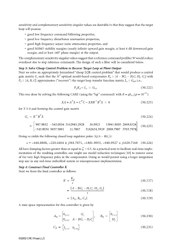
                       A state space representation for this controller is given by

                                           A K =  0 2 ×  2  G c    ,   B K =  0 2 ×  2         (30.230)
                                                        –
                                                 0 6 ×  2 ABG c –  H f C      H f
                                           C K =  I 2 × 2 0 2 × 6                              (30.231)


                       ©2002 CRC Press LLC

