Page 992 - The Mechatronics Handbook
P. 992

Human   u                Y
                                                                    operator        System
                                                   Sensor
                                                   Inputs

                                                                            u   +
                                                             X               m
                                                                               Σ
                                                                             −

                                                                            e
                                                                       BP

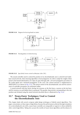
                                 FIGURE 33.20  Diagram for learning based on mimic.


                                                      X              u   u                 Y
                                                                       Σ        System
                                                                      −
                                                                         +

                                                                    e
                                                              BP


                                 FIGURE 33.21  Training phase at inverse learning.

                                                      r                    u               Y
                                                          X                      System


                                                                                        e y  −
                                                                  BP                       Σ
                                                                                          +


                                 FIGURE 33.22  Specialized inverse control architecture (after [50]).

                                   The neural controller used to control the position of an electrohydraulic axis is a feed-forward multi-
                                 layer neural network, whose learning algorithm is back-propagation. In order to adapt the weights which
                                 preserve the learned information, two steps are gone through with: a forward propagation procedure of
                                 the useful signal and a  backward propagation of the error. The control structure is implemented in
                                 SIMULINK as it is shown in Fig. 33.23. The neural control of the electrohydraulic axis and the achieve-
                                 ment of controller parameters are performed online.
                                   A neural network with four layers, having two neurons on the first layer, a neuron on the last layer,
                                 and five neurons on each hidden layer, is proposed. The graphic characteristic corresponding to the axis
                                 position and obtained using the neural network described above is illustrated in Fig. 33.24.
                                 33.7 Neuro-Fuzzy Techniques Used to Control
                                         the Electrohydraulic Axis
                                 This chapter deals with several computer-aided design techniques of hybrid control algorithms. This

                                 paper concentrates on these types of algorithms, because the performances achieved through simulation
                                 of an electrohydraulic axis with a neuro-fuzzy controller are comparable or superior to those yielded by
                                 other control algorithms. Taking into account the novelty of neuro-fuzzy algorithms and the absence in

                                 ©2002 CRC Press LLC
   987   988   989   990   991   992   993   994   995   996   997