
Page 338 - Thermal Hydraulics Aspects of Liquid Metal Cooled Nuclear Reactors
P. 338
Simulation of flow-induced vibrations in tube bundles using URANS 307
6.2.2.3.5 The post-divergence regime
The weakly nonlinear theory (Modarres-Sadeghi et al., 2008) predicts that flutter
around the buckled state will happen after the divergence region. Experimentally,
however, flutter became visible at much lower flow velocities and around the neutral
centerline. In previous linear analysis, a condition for flutter was derived from
Paı ¨doussis (2004), stating that the amount of work done on the system must be pos-
itive. The presence of the different force coefficients in the expression for the work
means that a good prediction of viscous forces is required to assess whether flutter
is going to happen or not.
According to the present computational results, the structure restabilizes right after
the divergence regime. In contrast to the results in the first stable regime, the transient
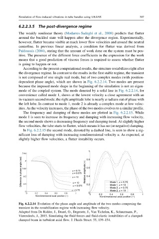
is not composed of one single real mode, but of two complex modes (with position-
dependent phase angle), which are shown in Fig. 6.2.2.14. Two modes are present
because the imposed mode shape in the beginning of the simulation is not an eigen-
mode of the coupled system. The mode denoted by a solid line in Fig. 6.2.2.14, for
convenience called mode 1, shows at the lowest velocity a close agreement with an
in-vacuum second mode; the right amplitude lobe is nearly π radians out of phase with
the left lobe. In contrast to mode 1, mode 2 is already a complex mode at low veloc-
ities. As the velocity increases, the phase of the two modes evolves to a similar profile.
The frequency and damping of these modes are plotted in Fig. 6.2.2.15. While
mode 1 is seen to increase its frequency and damping with increasing flow velocity,
the second mode shows a decreasing frequency and damping trend. At slightly higher
flow velocities, the tube starts to flutter, which means it has no (or negative) damping.
In Fig. 6.2.2.15 the second mode, denoted by a dashed line, is seen to show a sig-
nificant loss of damping with increasing nondimensional velocity u. As expected, at
slightly higher flow velocities, a flutter instability occurs.
Fig. 6.2.2.14 Evolution of the phase angle and amplitude of the two modes composing the
transient in the restabilization regime with increasing flow velocity.
Adapted from De Ridder, J., Doar e, O., Degroote, J., Van Tichelen, K., Schuurmans, P.,
Vierendeels, J., 2015. Simulating the fluid forces and fluid-elastic instabilities of a clamped-
clamped beam in turbulent axial flow. J. Fluids Struct. 55, 139–154.