
Page 333 - Thermal Hydraulics Aspects of Liquid Metal Cooled Nuclear Reactors
P. 333
302 Thermal Hydraulics Aspects of Liquid Metal Cooled Nuclear Reactors
centrifugal fluid force becomes more important). At a given velocity, the tube will
buckle in a ground mode shape and show small-amplitude vibrations around this buck-
led state due to turbulence. The amplitude of the buckling increases with increasing
flow velocity. The onset of buckling is also marked by a vanishing ground mode fre-
quency. At even higher flow velocities, the tube starts to flutter around its initial
straight position. Eventually, there is a small regime of restabilization in between
the divergence (buckling) and flutter regime. Note that the maximal displacement
in Fig. 6.2.2.7 consists of the sum of steady and unsteady contributions.
6.2.2.3.2 Methodology
The modal characteristics of a tube in the unstable region are determined with the
methodology published earlier in De Ridder et al. (2013). Briefly summarized, this
methodology consists of four steps:
1. Compute in-vacuum eigenmodes of the structure.
2. Deform solid and fluid domain with scaled eigenmodes.
3. Compute the free vibration decay (w(z,t)) using a coupled CFD-CSM computation with a
partitioned but fully coupled approach (Degroote et al., 2009).
P c i t
4. Fit a modal expression to the computed decay (w(z,t) a i (z)e sin(ω i t+φ i (z))).
Note that the initially imposed in-vacuum mode of the structure alone does not nec-
essarily agree with the modes of the fluid and structure together.
The numerical settings are identical to those in the previous section. As turbulent
eddies are not explicitly resolved, it is impossible to predict the turbulence-induced
vibration part in Fig. 6.2.2.7 with the present computations. As inlet conditions, a very
low inlet turbulence level is applied, so that turbulence in the flow is generated by the
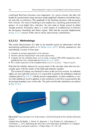
developing boundary layer on the tube. The grids used for the simulations are plotted
in Fig. 6.2.2.8.
Fig. 6.2.2.8 Cross-sectional view of the meshes, with the fluid mesh in blue and the solid mesh
in gray.
Adapted from De Ridder, J., Doar e, O., Degroote, J., Van Tichelen, K., Schuurmans, P.,
Vierendeels, J., 2015. Simulating the fluid forces and fluid-elastic instabilities of a clamped-
clamped beam in turbulent axial flow. J. Fluids Struct. 55, 139–154.