
Page 332 - Thermal Hydraulics Aspects of Liquid Metal Cooled Nuclear Reactors
P. 332
Simulation of flow-induced vibrations in tube bundles using URANS 301
at the same axial coordinate, both streets are typically π radians out of phase. Conse-
quently, the vibration of tube 1 in the x-direction is stronger than in the y-direction.
6.2.2.3 Movement-induced vibration
In this section, a methodology based on coupled CFD and CSM computations to deter-
mine modal characteristics of a structure in contact with a (turbulent) flow (De Ridder
et al., 2013) is applied to compute the dynamics in a broad range of flow velocities
(including the unstable regime) of the clamped-clamped tube in turbulent axial flow
of Modarres-Sadeghi et al. (2008). The next sections present a description of the
experiment and a description of the methods used. In the analysis, the subcritical
dynamics are discussed, followed by an analysis of the buckling regime, and finally,
the postdivergence regime is treated.
6.2.2.3.1 Description of the experiment
The experimental setup in Modarres-Sadeghi et al. (2008) consists of a water loop in
which a transparent test section with a length of 75cm and a diameter of 20cm is
mounted vertically. It is assumed that a flat velocity profile exists 2.5cm away from
the test section walls. Information on turbulence levels is however not available. In
this test section, a (very) flexible, hollow tube is mounted, consisting of silicone rub-
ber. The outer tube diameter D o is 0.0156m, the inner tube diameter D i is 0.0094m,
and the length L is 0.435m. Generally, the system behaves as follows as the flow
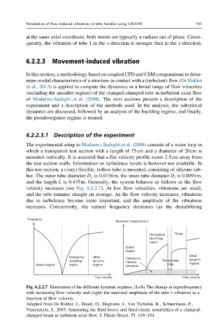
velocity increases (see Fig. 6.2.2.7). At low flow velocities, vibrations are small,
and the tube remains straight on average. As the flow velocity increases, vibrations
due to turbulence become more important, and the amplitude of the vibrations
increases. Concurrently, the natural frequency decreases (as the destabilizing
Frequency
Maximum displacement
Divergence Flutter
(buckling)
region
Stable
regime
Other
Divergence Other Turbulence-
(buckling) dynamic induced Restablizing dynamic
Stable regime region regions vibrations zone regions
Flow velocity Flow velocity
Fig. 6.2.2.7 Illustration of the different dynamic regimes. (Left) The change in eigenfrequency
with increasing flow velocity and (right) the maximal amplitude of the tube’s vibration as a
function of flow velocity.
Adapted from De Ridder, J., Doar e, O., Degroote, J., Van Tichelen, K., Schuurmans, P.,
Vierendeels, J., 2015. Simulating the fluid forces and fluid-elastic instabilities of a clamped-
clamped beam in turbulent axial flow. J. Fluids Struct. 55, 139–154.