
Page 488 - Bird R.B. Transport phenomena
P. 488
468 Chapter 15 Macroscopic Balances for Nonisothermal Systems
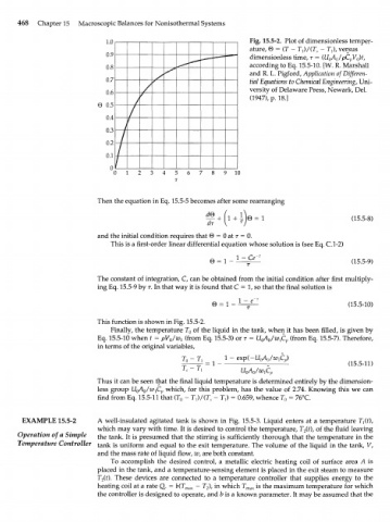
1.0 Fig. 15.5-2. Plot of dimensionless temper-
ature, 0 = (T - TJ/(T, - 7V, versus
0.9 dimensionless time, т = (UoA /pC V )t,
0
p
0
0.8 according to Eq. 15.5-10. [W. R. Marshall
and R. L. Pigford, Application of Differen-
0.7 tial Equations to Chemical Engineering, Uni-
/
0.6 versity of Delaware Press, Newark, Del.
(1947), p. 18.]
0 0.5
/
0.4
f
0.3
/
0.2
/
0.1
/
0 1 7 8 9 10
Then the equation in Eq. 15.5-5 becomes after some rearranging
(15.5-8)
and the initial condition requires that 0 = 0 at r = 0.
This is a first-order linear differential equation whose solution is (see Eq. C.I-2)
- Ce
6 = 1 - (15.5-9)
The constant of integration, C, can be obtained from the initial condition after first multiply-
ing Eq. 15.5-9 by т. In that way it is found that С = 1, so that the final solution is
0 = 1 - 1 - e~ (15.5-10)
This function is shown in Fig. 15.5-2.
Finally, the temperature T of the liquid in the tank, when it has been filled, is given by
o
Eq. 15.5-10 when t = pV /w^ (from Eq. 15.5-3) or r = UQAQ/W^ (from Eq. 15.5-7). Therefore,
0
in terms of the original variables,
= 1 - (15.5-11)
- Г,
Thus it can be seen that the final liquid temperature is determined entirely by the dimension-
less group UQAQ/IV^CP which, for this problem, has the value of 2.74. Knowing this we can
find from Eq. 15.5-11 that (T - TJ/(T S - T,) = 0.659, whence T = 76°C.
o
o
EXAMPLE 15.5-2 A well-insulated agitated tank is shown in Fig. 15.5-3. Liquid enters at a temperature 7^(0,
which may vary with time. It is desired to control the temperature, T (t), of the fluid leaving
2
Operation of a Simple the tank. It is presumed that the stirring is sufficiently thorough that the temperature in the
Temperature Controller tank is uniform and equal to the exit temperature. The volume of the liquid in the tank, V,
and the mass rate of liquid flow, w, are both constant.
To accomplish the desired control, a metallic electric heating coil of surface area A is
placed in the tank, and a temperature-sensing element is placed in the exit steam to measure
T (t). These devices are connected to a temperature controller that supplies energy to the
2
heating coil at a rate Q e = b(T max - T ), in which T max is the maximum temperature for which
2
the controller is designed to operate, and b is a known parameter. It may be assumed that the