
Page 486 - Bird R.B. Transport phenomena
P. 486
466 Chapter 15 Macroscopic Balances for Nonisothermal Systems
Table 15.5-1 Unsteady-State Macroscopic Balances for Flow in Nonisothermal Systems
Mass:
•S 2 (A)
Momentum: 31 Ptot Щ + wi tot g - ¥ Hs (B)
at
Angular momentum: — I — w, r, X u,] - u 2 ] + T ext - T ^
dt to t (C)
Mechanical energy: w _i_ ш _ p _ p
(D)
(Total) energy: + U ) = + H )w + W + Q
ы tot 2 2 m (E)
Notes:
" Xw ] = w ]a + w ]b + Wi c + • • •, where z^ lrt = P\ a v la S ]a/ and so on.
b /i] and /i 2 are elevations above an arbitrary datum plane.
c are enthalpies per unit mass relative to some arbitrarily chosen reference state; the formula for H is given in Eq. 9.8-8.
H ] and H 2
d All equations are written for compressible flow; for incompressible flow, E c = 0. The quantities E c and E v are defined in Eqs. 7.3-3 and 4.
c \x x and u 2 are unit vectors in the direction of flow.
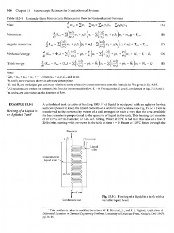
EXAMPLE 15.5-1 A cylindrical tank capable of holding 1000 ft 3 of liquid is equipped with an agitator having
sufficient power to keep the liquid contents at a uniform temperature (see Fig. 15.5-1). Heat is
Heating of a Liquid in transferred to the contents by means of a coil arranged in such a way that the area available
an Agitated Tank f or h t transfer is proportional to the quantity of liquid in the tank. This heating coil consists
e a
of 10 turns, 4 ft in diameter, of 1-in. o.d. tubing. Water at 20°C is fed into this tank at a rate of
20 lb/min, starting with no water in the tank at time t = 0. Steam at 105°C flows through the
Liquid
inlet
Instantaneous
liquid level
Fig. 15.5-1. Heating of a liquid in a tank with a
Condensate out variable liquid level.
1
This problem is taken in modified form from W. R. Marshall, Jr., and R. L. Pigford, Applications of
Differential Equations to Chemical Engineering Problems, University of Delaware Press, Newark, Del. (1947),
pp. 16-18.