
Page 489 - Bird R.B. Transport phenomena
P. 489
§15.5 Use of the Macroscopic Balances to Solve Unsteady-State Problems 469
Temperature
/ indicator
Power
supply
Liquid
Temperature outlet
controller
Electric -
heater Agitator
Liquid _
inlet
= T 10 (for t < 0)
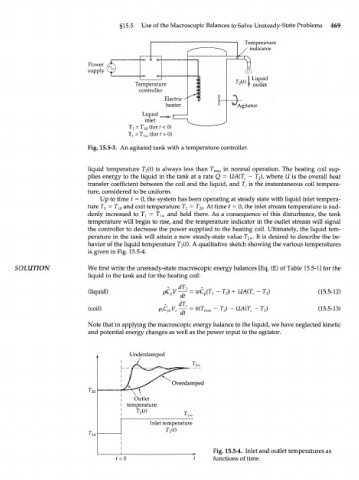
Fig. 15.5-3. An agitated tank with a temperature controller.
liquid temperature T 2(t) is always less than T max in normal operation. The heating coil sup-
plies energy to the liquid in the tank at a rate Q = UA(T C — T 2), where U is the overall heat
transfer coefficient between the coil and the liquid, and T c is the instantaneous coil tempera-
ture, considered to be uniform.
Up to time t = 0, the system has been operating at steady state with liquid inlet tempera-
ture T] = T 10 and exit temperature T 2 = T 20 . At time t = 0, the inlet stream temperature is sud-
denly increased to 7^ = T l00 and held there. As a consequence of this disturbance, the tank
temperature will begin to rise, and the temperature indicator in the outlet stream will signal
the controller to decrease the power supplied to the heating coil. Ultimately, the liquid tem-
perature in the tank will attain a new steady-state value T 2x. It is desired to describe the be-
havior of the liquid temperature T 2(t). A qualitative sketch showing the various temperatures
is given in Fig. 15.5-4.
SOLUTION We first write the unsteady-state macroscopic energy balances [Eq. (E) of Table 15.5-1] for the
liquid in the tank and for the heating coil:
(liquid) , - T 2) + UA(T C - T 2) (15.5-12)
dt
(coil) ftC Fy f -£ = b(T max - T 2) - UA(T C - T 2) (15.5-13)
Note that in applying the macroscopic energy balance to the liquid, we have neglected kinetic
and potential energy changes as well as the power input to the agitator.
Underdamped
Overdamped
\
Outlet
temperature
T 2(t)
Inlet temperature
T }(t)
_^ Fig» 15.5-4. Inlet and outlet temperatures as
f = 0 t functions of time.