
Page 484 - Bird R.B. Transport phenomena
P. 484
464 Chapter 15 Macroscopic Balances for Nonisothermal Systems
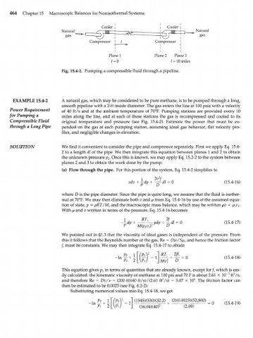
Cooler | I Cooler
Natural Natural
gas gas
Compressor j / Compressor
I I
I I
Plane 1 Plane 2 Plane 3
/ = 0 / = 10 miles
Fig. 15.4-2. Pumping a compressible fluid through a pipeline.
EXAMPLE 15.4-2 A natural gas, which may be considered to be pure methane, is to be pumped through a long,
smooth pipeline with a 2-ft inside diameter. The gas enters the line at 100 psia with a velocity
Power Requirement of 40 ft/s and at the ambient temperature of 70°F. Pumping stations are provided every 10
for Pumping a miles along the line, and at each of these stations the gas is recompressed and cooled to its
Compressible Fluid original temperature and pressure (see Fig. 15.4-2). Estimate the power that must be ex-
through a Long Pipe pended on the gas at each pumping station, assuming ideal gas behavior, flat velocity pro-
files, and negligible changes in elevation.
SOLUTION We find it convenient to consider the pipe and compressor separately. First we apply Eq. 15.4-
2 to a length dl of the pipe. We then integrate this equation between planes 1 and 2 to obtain
the unknown pressure p . Once this is known, we may apply Eq. 15.2-2 to the system between
2
planes 2 and 3 to obtain the work done by the pump.
(a) Flow through the pipe. For this portion of the system, Eq. 15.4-2 simplifies to
1
vdv + ^ (15.4-16)
where D is the pipe diameter. Since the pipe is quite long, we assume that the fluid is isother-
mal at 70°F. We may then eliminate both v and p from Eq. 15.4-16 by use of the assumed equa-
tion of state, p = pRT/M, and the macroscopic mass balance, which may be written pv = p^v^.
With p and v written in terms of the pressure, Eq. 15.4-16 becomes
(15.4-17)
We pointed out in §1.3 that the viscosity of ideal gases is independent of the pressure. From
this it follows that the Reynolds number of the gas, Re = Dw/Sfi, and hence the friction factor
/, must be constants. We may then integrate Eq. 15.4-17 to obtain
2fL
(15.4-18)
This equation gives p in terms of quantities that are already known, except for /, which is eas-
2
2
ily calculated: the kinematic viscosity of methane at 100 psi and 70 F is about 2.61 X 10 n ft /s,
6
2
and therefore Re = Dv/v = (200 ft)(40 ft/s)/(2.61 ft /s) = 3.07 X 10 . The friction factor can
then be estimated to be 0.0025 (see Fig. 6.2-2).
Substituting numerical values into Eq. 15.4-18, we get
№- J (1545X530X32.2) | (2)(0.0025)(52,800) _ (15.4-19)
2
(16.04X40)
(2.00)