Page 485 - Bird R.B. Transport phenomena
P. 485
§15.5  Use of the Macroscopic Balances to Solve Unsteady-State Problems  465

                           or

                                                              f
                                                  -In  ^  +  513 ^j  -  1  +  132 = 0          (15.4-20)
                           By solving this equation with p } =  100 psia, we obtain p 2 = 86 psia.
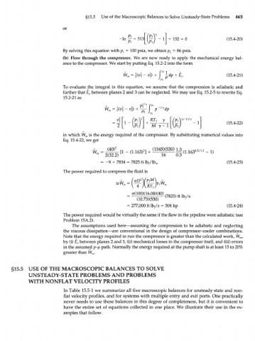
                           (b)  Flow through  the  compressor.  We are now  ready  to apply  the  mechanical  energy  bal-
                           ance to the compressor. We start by putting Eq. 15.2-2 into the  form

                                                              2
                                                        = \{v\ -v 2)  +  j-dp                  (15.4-21)
                                                    W m                   + E v
                                                                     P
                                                                   J P2
                           To evaluate  the  integral  in  this  equation,  we  assume  that  the  compression  is adiabatic  and
                           further  that E v between planes 2 and 3 can be neglected. We may use Eq. 15.2-5 to rewrite Eq.
                           15.2-21 as


                           in which  W M is the energy required  of the compressor.  By substituting numerical values into
                           Eq. 15.4-22, we get


                                             -
                                           = 9  +  7834 =  7825 ft lb //lb m                   (15.4-23)
                           The power required to compress the fluid  is


                                                      =  277,000 ft  %/s  =  504 hp            (15.4-24)
                           The power required would be virtually the same if the flow in the pipeline were adiabatic (see
                           Problem 15A.2).
                               The assumptions  used  here—assuming  the compression  to be adiabatic  and  neglecting
                           the viscous dissipation—are  conventional  in the design  of compressor-cooler  combinations.
                           Note that the energy required  to run  the compressor  is greater than the calculated  work, W m,
                           by (i) E v between planes 2 and 3, (ii) mechanical losses in the compressor itself, and  (iii) errors
                           in the assumed p-p path. Normally the energy required at the pump shaft  is at least 15 to 20%
                           greater than W nr


             USE OF THE MACROSCOPIC          BALANCES TO SOLVE
             UNSTEADY-STATE       PROBLEMS AND       PROBLEMS
             WITH NONFLAT VELOCITY PROFILES
                           In Table  15.5-1 we summarize  all five  macroscopic balances  for unsteady  state and  non-
                            flat  velocity profiles, and  for  systems with multiple entry and  exit ports. One practically
                            never needs  to use these balances  in this degree  of completeness, but  it is convenient  to
                           have the entire  set  of equations  collected  in one place. We illustrate  their  use in the ex-
                            amples that  follow.

