
Page 52 - Using ANSYS for Finite Element Analysis A Tutorial for Engineers
P. 52
IntroductIon to FInIte element AnAlysIs • 39
Where [K] is an 10 × 10 before deleting rows and column to account for
the fixed boundary support at nodes 1, 3, and 4.
Assemblage of stiffness matrix
The stiffness matrix for element is:
[k] = tA[B] [D] [B]
T
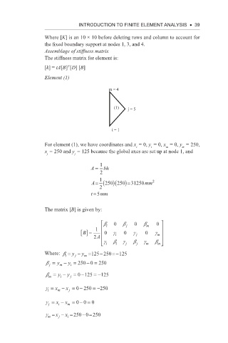
Element (1)
m = 4
(1) j = 5
i = 1
For element (1), we have coordinates and x = 0, y = 0, x = 0, y = 250,
m
i
i
m
x = 250 and y = 125 because the global axes are set up at node 1, and
j j
A = 1 bh
2
1 2
A= (250 )(250 )=31250 mm
2
t =5 mm
The matrix [B] is given by:
b i 0 b j 0 b m 0
B [] = 1 0 g i 0 g j 0 g m
2 A
g i b i g j b j g m b m
m
j
−
Where: b = y − y =125 250 =−125
i
b = y − y = 250 − = 250
0
i
m
j
b = y − y =−125 =−125
0
m
i
j
g = x − x =− 250 =−250
0
i
j
m
00
g = x − x =−= 0
i
j
m
0
g = x − x = 250 − = 250
m
i
j