
Page 56 - Using ANSYS for Finite Element Analysis A Tutorial for Engineers
P. 56
IntroductIon to FInIte element AnAlysIs • 43
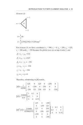
Element (3)
j = 3
m = 5 (3)
i = 2
A= 1 bh
2
1 2
A= (250 )(250 )=31250 mm
2
For element (3), we have coordinates x = 500, y = 0, x = 250, y = 125,
m
i
m
i
x = 500 and y = 250 because the global axes are set up at node 1, and
j
j
b = y − y =125
j
i
m
b = y − y =125
i
m
j
b = y − y =− 250
m
i
j
g = x − x =− 250
m
i
j
g = x − x = 250
m
j
i
g = x − x =0
i
j
m
Therefore, substituting in [B] matrix,
125 0 125 0 −250 0
B []= 1 0 −250 0 250 0 0
62500
− 250 125 250 125 0 −250
1 0 3 . 0
D []= 210000 03 . 1 0
091
.
0 0 035
.
125 0 −250
0 −250 125 1 0 3 . 0
T
B [] []= 210000 125 0 250 03 . 1 0
D
(.
62500 091) 0 250 125 035
−250 0 0 0 0 .
0
0 0 − 250 