
Page 54 - Using ANSYS for Finite Element Analysis A Tutorial for Engineers
P. 54
IntroductIon to FInIte element AnAlysIs • 41
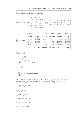
The stiffness matrix for element (1) is:
−125 −37 5 . −875 .
−75 −250 −43 75
.
− 125 5 0 250 0 − 125 0
)
5
k [] = ()(31250 )(3 6923 250 75 0 × 1 0 − 250 0 0 0 250
.
0 0 8775. 62500 − 250 − 125 0 250 250 − 125
− 125 − 37 5 875
.
.
75 250 − 43 75
.
37500 20313 −31250 −21875 −6250 1563
− −
20313 67969 −18750 −110938 1563 57031
− 31250 − 18750 6250 0 − 31250 18750
k [] = 9 2308
.
− 21875 − 10938 0 2 21875 21875 − 10938
− 6250 − 1563 − 31250 21875 37500 − 20313
1563 − 57031 18750 − 10938 − 20313 67969
1
Element (2)
m = 5
(2)
i = 1 j = 2
A = 1 bh
2
1 2
A= (500 )(125 )=31250 mm
2
For element (2), we have coordinates x = 0, y = 0, x = 250, y = 125,
i
m
i
m
x = 250 and y = 0 because the global axes are set up at node 1, and
j j
b = y − y =−125
m
i
j
b = y − y = 125
m
j
i
b = y − y = 0
i
m
j
g = x − x =−250
i
j
m
g = x − x =−250
i
j
m
g = x − x = 500
m
j
i